


18-03/04 Skins, Top Stiffeners, Baffles & Attach Brackets
I decided to leave the external vinyl in place apart from the rivet lines & edges, using the usual soldering iron technique.
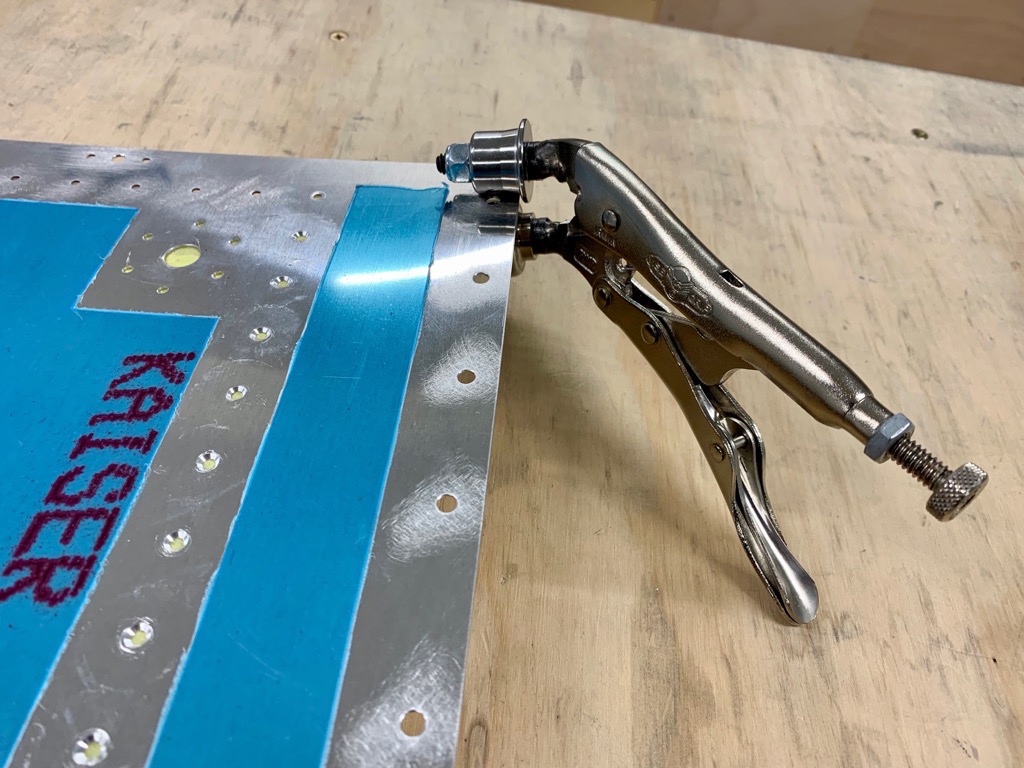
Skin edge Deburring
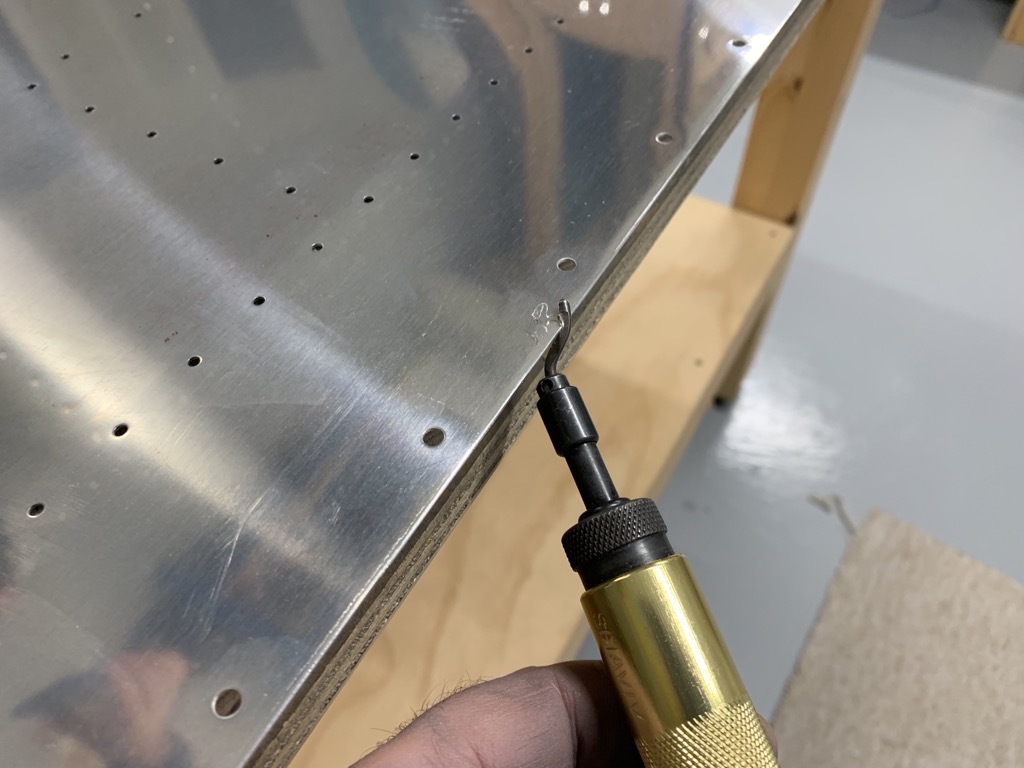
After gently removing the little “saw teeth” with a file, I used a deburring tool to remove the sharp edges …

… and then a sanding block with 320 grit to finish the edges. I didn’t want to remove any more material than absolutely necessary, since Vans stipulate a max gap between the tank skin and wing skin when assembled (0 – 0.4mm)
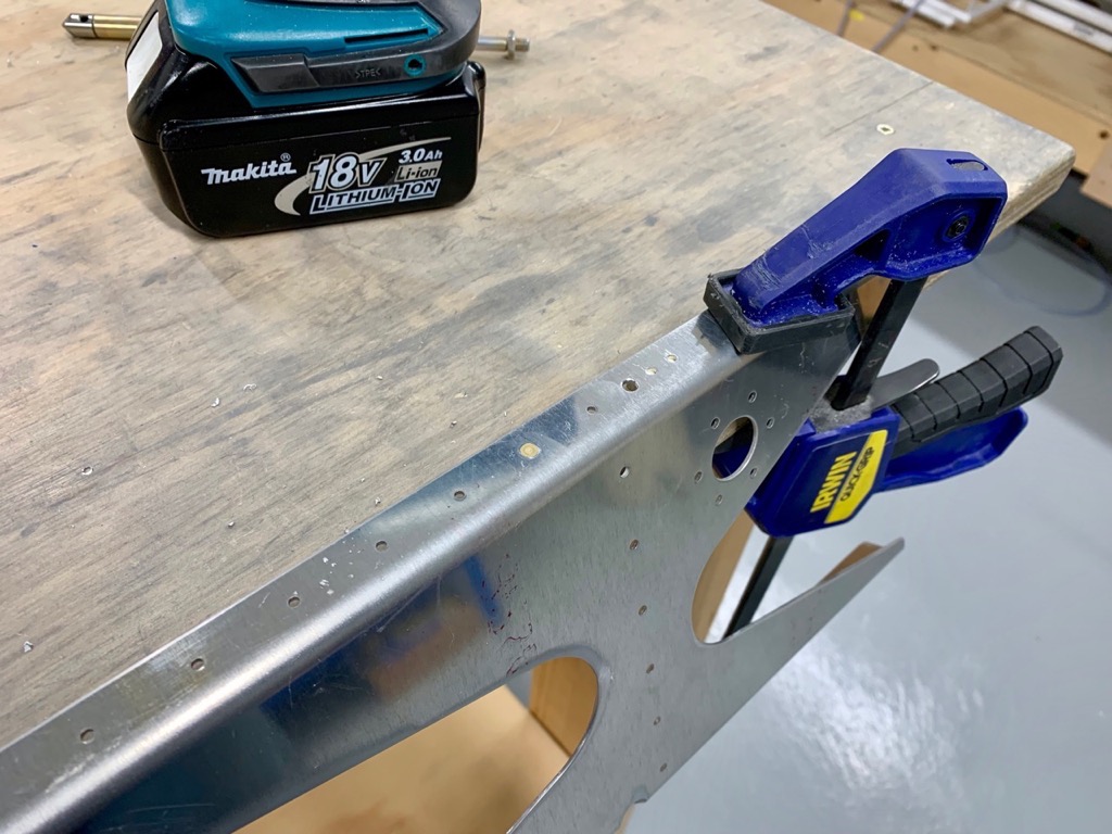
Top Stiffeners
The top stiffeners are fabricated from J-Channel in the same way as for the LE’s. Having marked a rivet line, and drilled the first hole, the J-Channel is match drilled with the skin, inserting clecoes as you go.
I found that fixing the J-Channel either side of a rib span, and then match drilling between worked pretty well.

I used a peice of wood to keep the J-Channel firmly in place as I drilled. This technique needed a rib in place to act as support.
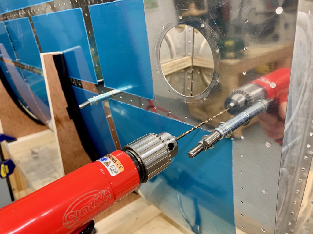
Machine Countersinking the Tank Skins
I clecoed the ribs and tank baffles onto the skins.
This proved far from easy, as the ribs are an extremely tight fit around the leading edge. I found that by clecoeing the first few bottom holes on the ribs, and then the top holes from the rib nose backwards was the best way. Going to have to come up with a cunning plan to make this easier when Proseal is about!!!

Every 10th hole is not machined, to ensure the baffle is accurately postioned whilst rivetting. Once the sealant has cured after final assembly, these last holes are machined and sealed.
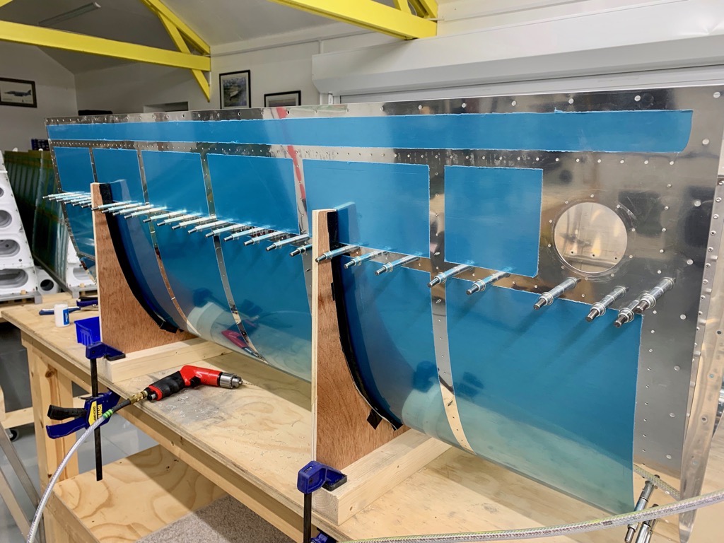
Breaking Edges & Dimpling
Vans says to “break” the aft edges … I also did the outboard edge, where it will butt up to the inner LE skin.

The DRDT2 was again brilliant for dimpling the skins. I masked off the holes which do not have dimples to avoid tears! I again scuffed the rivet lines prior to dimpling.

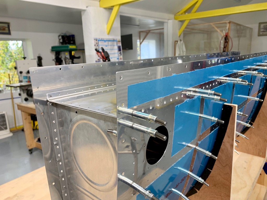
Attach Brackets
The Attach Brackets are machine countersunk to allow for .032″ skin dimples. But the flange part which is outside the tank is countersunk for shim dimples, and the orientatation of these caused some head scratching. No problem, but easy to end up with two Left shims etc if you’re not careful! The manual does highlight this danger.
Fuel Cap Flanges
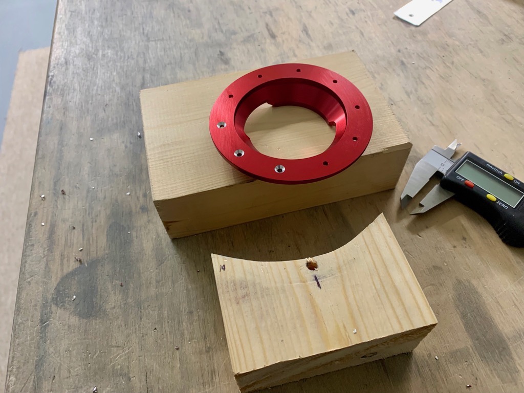
The fuel cap flanges are countersunk for 0.032″ skin dimples. I went a bit deeper than the usual +0.007″, since with just 0.007″ the flanges were not a nice fit on the skin dimples.
I cut a curve in a block of wood to provide good support during the machining.

So all the parts for the fuel tanks have now been prepared. There is no avoiding it … the next step involves use of the ProSeal … watch this space.
I have to go to work for a few days, so I’m going to leave the tanks assembled in the hope that it will gently form the skins around the rib noses and make the ribs easier to fit.


