


11-02 Attaching Elevators
Having finished the aft fuselage, I’ve been taking advantage of the better weather and doing some flying! My Fuselage & Wings shipment is due to arrive on Friday 1st June, and I’d like to get the empennage attachment done. I plan to take it all apart to store safely once everything is fits correctly.
Rod End Bearings

The first job is to rig the elevators, which means screwing in the rod end bearings. I was surprised how stiff these were to turn, so much so that I checked several times I wasn’t cross threading. Fingers were not enough, and I used mole grips with the bearings protected by a plastic thingy I found.

When subsequently adjusting the rod ends during final attachment after painting I used a Rod End Adjusting Tool … much better!


The manual suggests an initial guess for how far to insert, measured to the axis of the rod end hole. So I cut a piece of wood to the exact length minus half an AN3 bolt width.
First Elevator Fit
The elevators needed to be attached and de-attached lots of times during rod end adjustment to get the best fit. It was a bit of a fiddle, so I made some shims to align the rod ends with the tailplane brackets.
The width of the rod end bearings are an exact fit for the tailplane attachment brackets, hence also proved a fiddle to insert. I used a plastic coated spanner to gently splay the brackets allowing the rod ends to be more readily inserted.

Then another fiddle to insert the AN3 bolts! Plastic coated pliers this time!
Adjustments

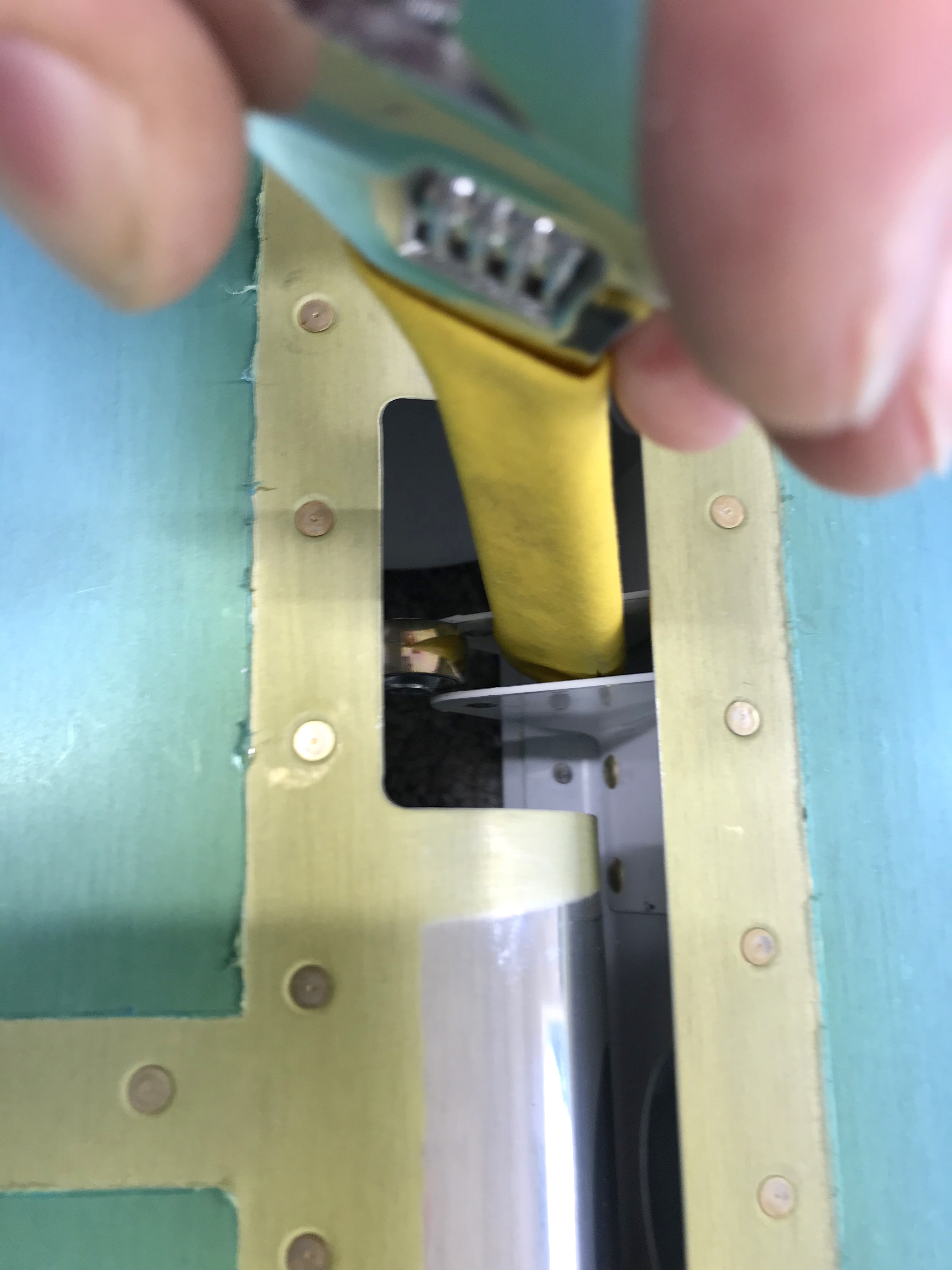
Several parameters need to checked, and manipulated by iterative adjustments of the individual rod ends. There is a min distance of the horns from the tailplane rear spar, so again I used a block of wood.

Then the travel of the elevators have to be checked – I used a digital level, which you can set to any reference. This made it quick and easy.
The gap between the counterbalances and tailplane ends also have to be a min width of 3.2mm. When I first attached the elevators, this was not correct. In fact it was because the counterbalances were not parallel to the tailplane ends, so yet another adjustment (screwing one rod end in, the other one out) solved that problem.
But this alters other things …. eg the down elevator travel. The maximum deflection down is restricted by the elevator horn hitting the stop on the tailplane rear spar flange. Hence another half turn out was needed to ensure enough travel.
I was faced with imperfect manufacture of the elevator horns. I don’t think the powder coated steel parts are up to the quality of the rest of the kit. In hindsight I wish I had checked the horns more carefully for geometrical accuracy – my left one was not made well at all. It isn’t quite at right angles, and also welded to a different angle on the tube.
Inspect yours carefully before attaching in section 9-17.
Anyway, annoying but not unsurmountable …. I had to carry out yet more small adjustments to make sure the holes which will be drilled in the horns during rigging were the best compromise for both horns, keeping edge distances in mind!
Finally the rolled leading edges need to be checked for clearance from the tailplane rear skins. This was fine and needed no adjustment thank goodness!


