


33-04 to 10 Rudder Pedals & Beringer Brakes
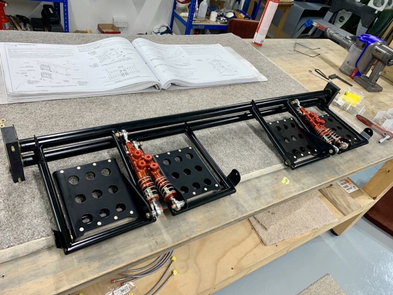
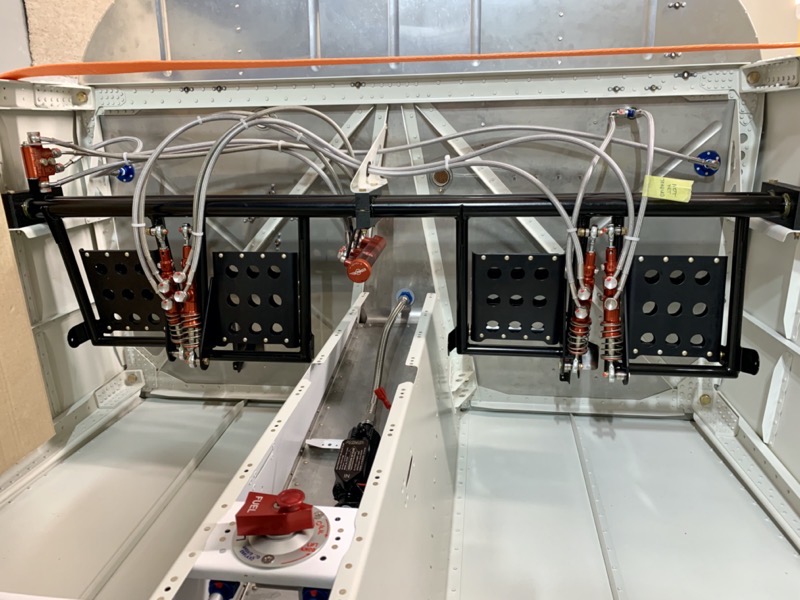
The picture above shows the brake system installed … it took a bit of head scratching to get there!

These are all the parts supplied by Beringer, which are all very nice quality.
The Beringer RV14 manual seems to be based on the RV10, so a lot of part numbers do not relate to the 14. They also have updated some parts, so a few washer callouts etc don’t work.
But with a bit of test assembly and planning it all begins to make sense.
Brake Cylinders
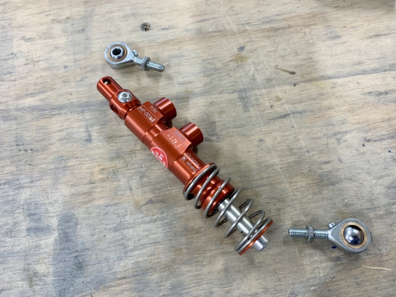
The Brake Cylinders arrived with the eye bolts unassembled, so the first job was to attach these and adjust to a suitable length.
As a first guess I’ve adjusted these to position the brake pedals parallel with the rudder pedal assembly. I’m not sure if this will need adjusting?
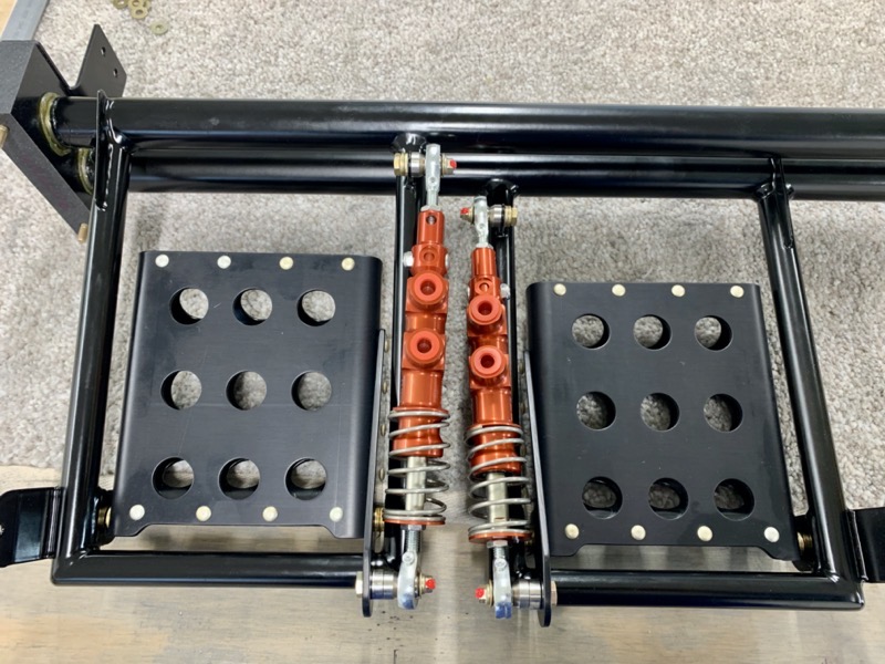
I test assembled the L & R pedals to ensure clearances.
Brake Regulator

I decided to fit the Beringer Brake Regulator, which apparently does a good job in balancing brake application L & R to help with keeping straight.

The manual suggests it is attached to the underside of the middle F-6115 Bearing Block, using a supplied bracket.
This seemed like a good plan, since although once adjusted you shouldn’t need to access it very often, in this position it’ll be easy.
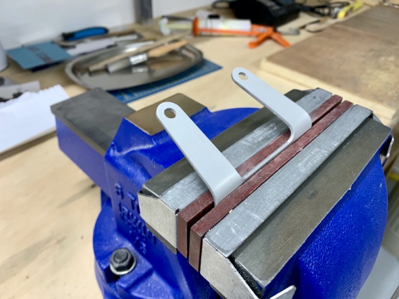
The bracket was supplied flat, so I bent the lugs to a suitable angle.
Here it is installed on the bottom of the middle bearing block.
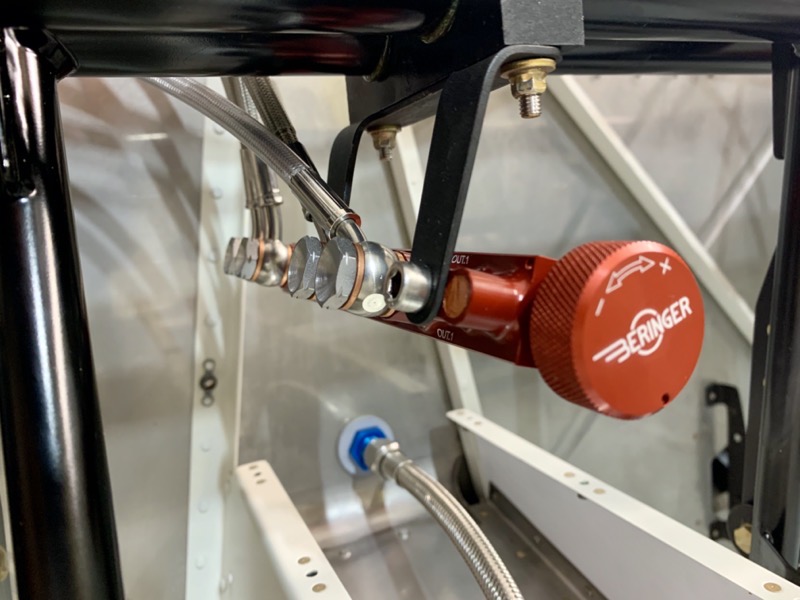
Parking Brake

The parking brake valve is installed on top of the left bearing block, again using a supplied bracket.
Hoses

The Beringer Manual has good diagrams showing how to couple all this up. This is the one relevant for my installation.
I have cheated again and purchased the excellent hoses produced by Tom Swearengen at TS Flightlines and sold by Aircraft Speciality.
Tom has produced a good manual with the hoses … the hose names do not match the Beringer manual, but it doesn’t take too long to sort it out.
Once all the components were in position, it didn’t take long to assemble the hoses.
I decided to position my rudder pedal assembly at the rear position. The hose from the Co-Pilot R pedal up to the reservoir is a little short I think … but I’m not sure on the exact angle of the pedals yet. I’ll know this once the rudder is linked.
I sent Tom an email asking about this, and he replied within minutes (on a Sunday!) … can’t ask more than that. He said he’d make me a longer one if required, but suggested I check it when rigged properly.


4 comments on 33-04 to 10 Rudder Pedals & Beringer Brakes
Please explain the two hoses to the left and right sides of the firewall (round blue connectors) What do they connect to and where are they on the flow diagram?
On page 33-10 of the manual it shows the FLF-00010 fittings, which basically allow the passage of brake line through the firewall via fittings. This is because the brake lines are routed down the front of the gear legs on the 14 taildragger. Note that on the 14A they are not required, since the brake lines go back to the main gear legs via the main spar.
And on page 40B-02 of the manual you’ll see that a connector is screwed into the FLF-00010’s so that the brake hoses can be routed down the front of the gear legs to the brake units.
In the Beringer schematic the FLF-00010’s are represented by the boxes which contain the words “original part 7/16” fitting”. I think the diagram is trying to incorporate details of the 14A and 14, making it a bit confusing.
More questions. Can you shed some light on operation of the Beringer anti-skid controller? It seems problematic that when the system is needed, on wet runways, one has only one chance to turn to knob to “get it right.” There should be a better way. The only instructions I could find from Beringer were in French. Also, how did you mount the pull control line for the parking brake? Any pictures of this? I have a similar parking brake on my RV-7A and have occasionally not remembered to release it finding that I had no brakes. One idea is to have a panel light that is on when the brake is active. Any other suggestions?
The Beringer lines from the parking brake control to the main gear run via several forward fuselage floor ribs and across the main bulkhead. The holes to accommodate the lines are sized for quarter inch plastic. The Beringer lines require enlargement of these rib holes to roughly half inch. The space to get this done is very small making a right angle attachment on a drill plus a step drill too long to get into these tight spaces. How did you enlarge these holes? Thanks.
Hi Jim
The Anti-Skid controller is not designed to be altered during flight, it must be set up on the ground by testing, then left to do its job. See https://www.beringer-aero.com/sites/beringer-aero.com/files/cata_usa.pdf for the Beringer info, page 131.
See https://vansrv14project.uk/fuselage/park-brake-beringer/ for how I installed the parking brake. You’ll see I included a microswitch to indicate on the G3X that the Park brake is ON. Also I positioned the knob throw so that when OFF it does not extend beyond the panel, hence giving a clear visual confirmation when OFF.
G-STRV is a 14, so I do not know about brake lines through rib holes.
Cheers
Steve