


19 – Wing Wiring Part 1
This section of the manual is all about installing the wing wiring and Pitot/AOA tubes. So, lots of design decisions have had to be made!
When at Oshkosh last year I very much admired Rick Thompson’s RV14, and one feature I noticed was the lighting in the wing tips. The AeroLED Nav/Strobes look very lost in the tip recess on their own, and Rick had solved this by also installing some AeroLED AeroSun Vx Landing/Taxy Lights.
Obviously we already have landing light provision in the wing leading edge, but you can never have enough conspicuity lighting? And then AeroLED via Vans offered some discount during the “Virtual Oshkosh” this year, so I talked myself into it! : )
Wiring Design
So having decided to fit the AeroSun’s, the wing wiring harness supplied by Vans will need to be altered. As I started researching, I discovered that AeroLED advise their wiring be screened, and offer the suggestion to use the screen as an earth return.
The Vans/Stein wiring does not comply with this advice. Now I know there are lots of RV14’s flying with the Vans wiring, and I’m sure it all works just fine. But having read lots of tips about “following the manufacturer’s advice”, I have decided to do the same.
The Vans wing harnesses also do not include CANBUS wiring, since they were designed with the Garmin GMU 22 in mind, which does not link via the CANBUS. Also, again following Garmin’s advice, they state on Page 2-23 of their April 2020 G3X Install Manual …

The supplied harness does not comply with this, since each section of the screen is earthed locally. Again, it obviously works, but isn’t as advised. Additionally, talking to a Garmin G3X Expert here in the UK, they say that you should avoid routing the CANBUS through unnecessary connectors. (Indeed, if possible, not even at the wing root!) The supplied harness to the Roll Servo adds a redundant connector near the servo. In fact the Pitch Servo has the same, plus the connector where the Aft Fuselage joins the front.
We are not building a private jet, so maybe a compromise is required?
My compromise is to re-wire the servo harnesses to avoid the added connectors, and to use higher quality CPC connectors at the wing root for the data wires. I will also earth the screens to the connector backshells as advised by Garmin. Also to run screened cable out to the lights, and to use the screen for an earth return.
So that basically means to produce my own wing wiring harnesses then! : (
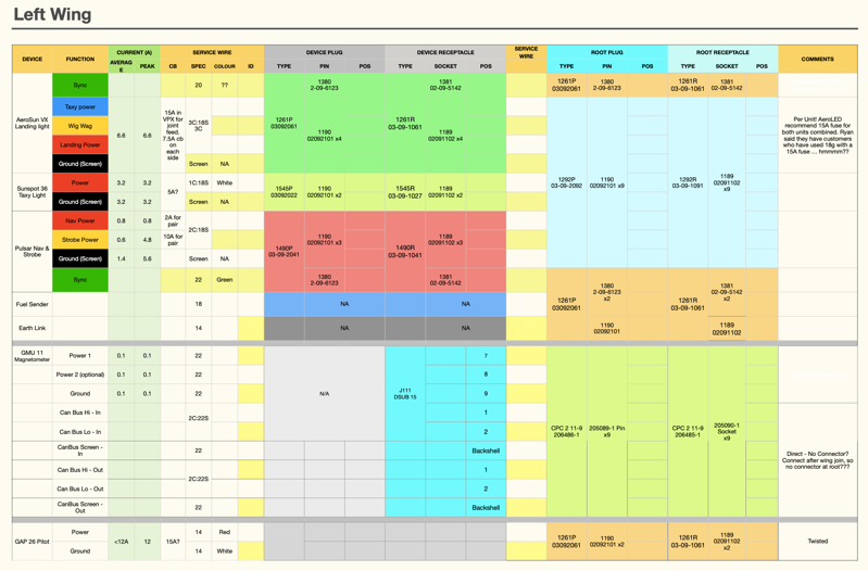
So I sat down and worked out which connectors and relevant terminals to buy.
This is a link to download the PDF version of the spreadsheet I used to work out a shopping list. Still work in progress! I found Mouser excellent, both for delivery and ease of finding items. My spreadsheet includes the part numbers, and if you pop them into the Mouser search box all is revealed!
This proved challenging, since when you search on Mouser or Digi-Key, there are so many variations it makes your head hurt!
In the end I plumped to stay with Molex 093″ for the lighting circuits, and use CPC Series 2 for the data wires, eg Magnetometer, CANBUS, Roll Servo & Aileron Trim.
If you have purchased a DMC AFM8 crimping tool with the necessary turrets for the Garmin Avionic terminals, then happily they will be suitable to crimp the CPC Series 2.
I did briefly look into using CPC Series 1 connectors for the lighting … these would be required due to the greater current rating … but it worked out very costly. Plus you need yet another flipping crimper! This has to stop somewhere!
Wire Routing Bushes

Having worked out the wires required, the next job was to decide how to route them.
I drew up a scale diagram of the HeyCo Bushes, and the number of wires to fit.

In the left wing I intend to route the lighting wires as specified in the Vans manual, but because I’ve extra wires and also need to route the 14awg Pitot Heat wires, the Bush A needed to be an SB 500-6. They were originally drilled for the smaller SB375-4. I want the Pitot Heat wires to be as far as possible from the magnetometer, hence the A position.
Holes B & C can be used to run the Pitot/AOA tubes, but nothing else with the standard bushes as specified in the kit.
The right wing is a bit easier, using C to route the RG400 if I decide to fit an Archer antenna. I did need to open up some existing holes to fit the aileron servo/trim wiring, since the AeroSun wiring used up available space in the kit specified bushes.
I needed some extra holes for the GMU 11 in the left wing, & the smallest bush for the wires is a SB375-4 …

… and this is how I did it. Having done this, and stood back and looked, I had a sudden panic that maybe it wasn’t a good idea.
I had read the advice on the Vans web site about extra holes in ribs etc, but the advice is generic.
Anyway, after a few days I couldn’t stand it any more, and owned up to Vans support! Happily I got a quick reply saying no problems, build on.

The obvious way to avoid a sleepless night is to ask Vans first about drilling extra rib holes!

I came up with a convoluted way to open up the holes to fit the larger SB500 bush.
This would be much easier with some kind of 90º drill attachment … it’s on my shopping list, since I think they’ll be more off this elsewhere!

I made some brackets to fit the extra connectors at the wing root …


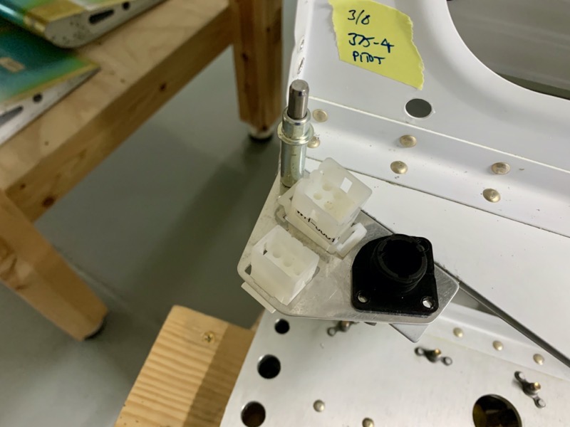
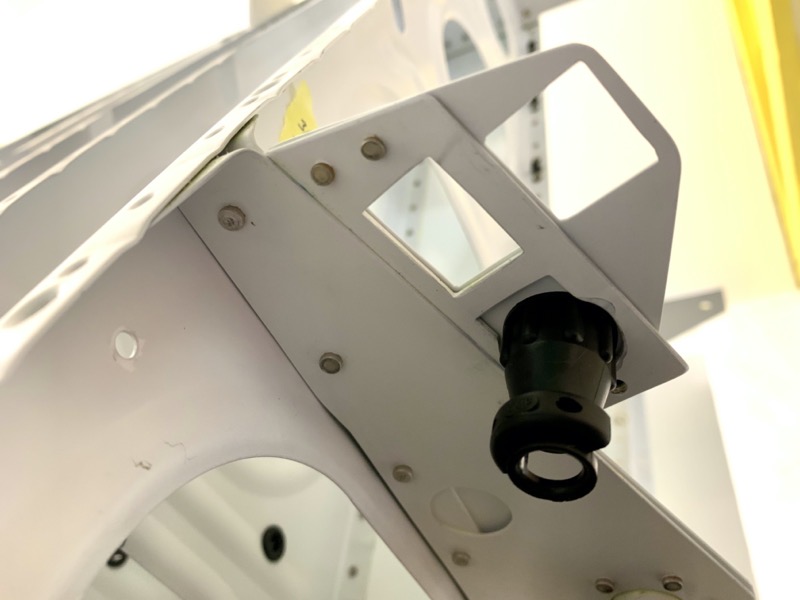
… and then worked out a way to secure them to the existing brackets.
There will be an extra connector at the tips to feed the AeroSun Vx’s, so I used an existing hole in the ribs to attach a bracket.
This has all taken a lot of time … it would be much easier to use Vans’ harness! : )


