


19 – Wing Wiring Part 2 – Lighting Harnesses
Having come up with an overall plan for the wing wiring, I decided to produce wiring diagrams detailing the wire sizes and connector pins to make it easier whilst making the harnesses.
They will also provide documentation for the future.
Just a reminder … I’m no expert at all this! What follows is my attempt to apply best practice after extensive research.
Wing Wiring Diagrams
I produced these in the style of the Vans (Stein) wiring harness diagrams, using a Mac software program called Graphic.
Here are links to download PDF’s of the three diagrams:
Left Wing
Right Wing
Right Wing – Servos
CanBus Deliberations

You’ll see from the diagrams I’ve changed my mind about how to run the CanBus. Garmin advise against unnecessary connectors in the CanBus, and having reconsidered, I’m going to attempt to connect it all up without running through the connectors at the wing roots. This will obviously not be very convenient, but possible.
I’m keeping the connectors as planned, with spare pin capacity to connect up the CanBus at the roots if it all proves too much.
Wing Light Wiring – Molex Fun
I decided to start with the lighting harnesses, and work from wing tip to wing root.
There are lots of videos explaining how to crimp Molex Pins/Sockets (best I found was by SteinAir), so after reminding myself of all the top tips, I couldn’t put off the job any longer!
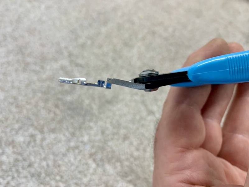
I trimmed the insulator wings slightly as appropriate for the wire sizes.

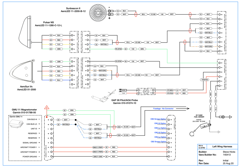
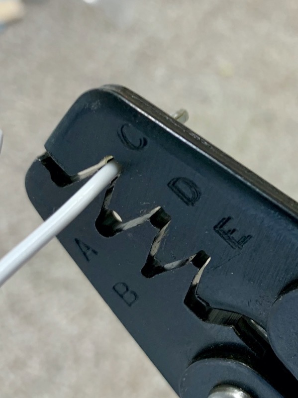
Talking of SteinAir, that is where I bought my Molex Crimper, which seems to work very well after a bit of practice.
I found position D was best for the wire crimp on 0.93″ pins.
Of course if you are prepared to spend lots of AMU’s (Aviation Monetary Unit) then it’s possible to buy a specialist ratchet crimping tool which does everything in one go : )
The crimper is positioned between the “wings” over the wire crimp tabs.

In ignorance I bought my Molex Pins/Sockets on a “reel”, and had to cut each one from the tape. Probably better to buy them separated.

The idea is to crimp with a little bit of wire protruding to prove all is crimped, making sure that the insulation is not captured at this stage, since this would disrupt the wire crimp strength.
A second crimp is required to capture the insulation, & position C seemed best on the wire I was using, but that would depend on insulator size etc.
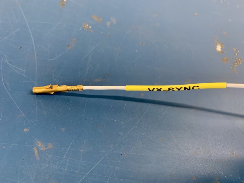
I used the standard pins on the higher current circuits, but slightly more expensive “gold” plated pins for data (low current) circuits.
My thinking was to preserve a low resistance at the connector as time goes on and oxidation sets in!
I labeled each wire at both ends using the names from the diagrams.
I made the labels using Dymo Heat Shrink Tube with a Dymo Rhino printer. It makes a nice and easy job, but the tube is pricey, so if you decide to use this method …
Printing as many names as possible in one print session with a space between them conserves the tube.
The machine spits out a lot of tube either side of the print job (see piccy, this was one of my first attempts).
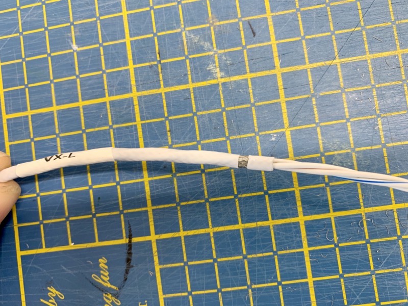
Screened Wire – Earth Return

As mentioned in a previous post, the AeroLED advice is to run screened cable and use the screen as an earth return.
So a wire needs to be soldered onto the screen at each end of the cable run, ready for a connector pin/socket.
This will be good practice for the Garmin CanBus wiring : )
Again, lots of advice available online, so this is how I did the job, following the workflow specified in the Raychem Solder Sleeve tech sheet … first carefully strip the insulation back by running a knife gently down the strip length, having made an axial cut at the required length …

… bunch up the screen, and snip it off …
… then remove about a 1/4″ of insulation, twisting as you slide it off. This keeps the screen end nice and flat …
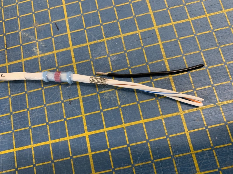
… you can either use solder sleeves or solder/heat shrink tube for this stage. I tried the solder/heat shrink, which works fine, but there is no doubt that a solder sleeve produces a better job. Trouble is, they are not cheap. I got some Raychem Solder Sleeves to try from Mouser. The number 2 and 3 sizes seemed the most suitable for the wire sizes I’m using.
It’s best to have the sleeve on the wire prior to removing the insulation … if you remember!
Then after positioning the earth wire, the sleeve is shrunk and the solder melted with a heat gun. The Raychem tech sheet advises a temp of 370ºC. I was concerned that this might cause issues with the Tefzel 22759 insulation, but it seems fine. I checked the continuities on each cable to ensure no insulation issues.
Interestingly, probably because of this concern, the Garmin install manual suggests the screen is peeled back over the cable outer insulation prior to positioning the solder sleeve. I used this method later on when wiring the GSA 28 Roll Servo connector, but the screen becomes distorted and I reckon the solder joint is not as good … hmmm?

The solder sleeves produce a secure and sealed joint.

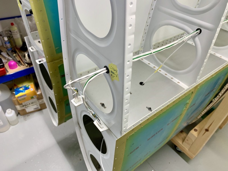
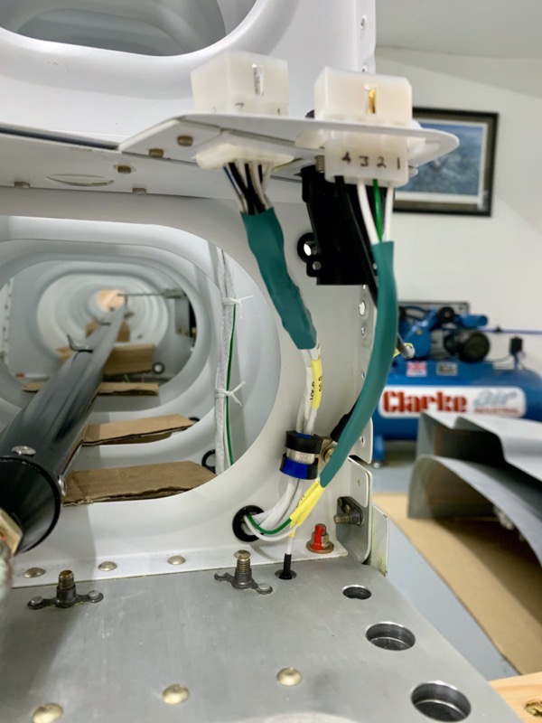
Having documented the wiring diagram, it was straightforward to follow the pin numbers and insert the pins into the correct holes.
I used a marker pen to highlight the pin numbers on the connectors … hard to see otherwise!

It’s best to twist the 14AWG pitot heat wire apparently, so I did this using my drill.
I found a reference somewhere suggesting 14AWG wire should have about 7 twists per foot.

I’m intending to anchor the pitot wire connector using a P-Clip … the hole in the spar web near the connector will be perfect … it’s the hole for the mechanical Stall Warner wire, which I’m not using.
Lacing
I then laced the wire harnesses, to ensure that the ends of the wires of the other end will be set correctly.
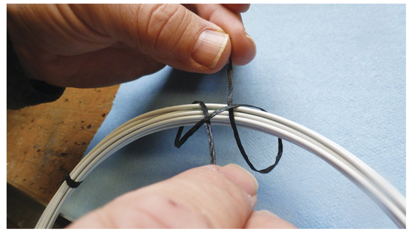
I used waxed lacing tape … these are pictures I found online showing a simple knot …

…
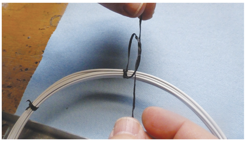
I found cutting 7″ lengths of lace worked well for each knot, cutting the ends of with a sharp knife once tied.
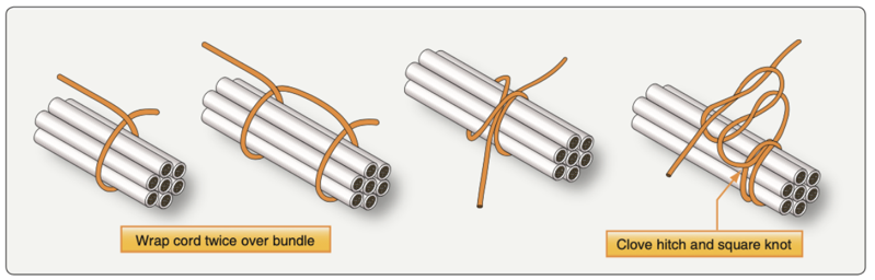

I tried to keep all the wires neatly bunched as I tied the knots.
This process “stiffened” the harness nicely.
Having routed the wires, with a deep breath, I cut them to equal length at each connector.
Of course the danger is that having cut the wires to the exact length, a disaster with a pin crimp would be an unhappy event! I cut the wires so that I could have 1 or 2 crimp attempts.
I took the time to check continuity between the pins in each connector, to double check each wire was correctly routed to the right pins!
Part 3 will show the data wiring (Servos and Magnetometer).


2 comments on 19 – Wing Wiring Part 2 – Lighting Harnesses
Looks very neat. What did you use for labeling? Printable heat shrink tubes?
That’s right Matthew – Dymo Heat Shrink Tube. I’ll update the blog to mention the printer/tube type