


VPX Wiring

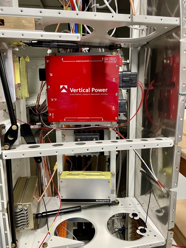
The Vertical Power VPX has 5 connectors, full of pins which have to be assigned to devices and switches. Obviously this takes a bit of planning, and there is a web based configuration tool which helps with this task. It’s an iterative process to produce an optimum configuration, since pins have different maximum CB values. Also, since the VPX effectively contains two separate Bus Bars it is best to integrate as much redundancy as possible eg PFD & MFD on different Bus Bars.
Having come up with a plan, I set about producing wiring diagrams for each connector, integrating with my previous diagrams for the rest of the aeroplane. On the left is an example, downloadable as a PDF here.
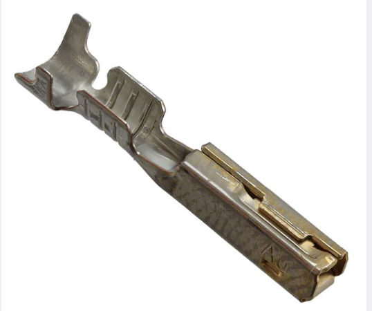
The VPX connectors are Molex 150L Series.
VPX sell a wiring kit with these terminals already crimped onto various lengths and gauge of wire, but as I already had wire supplies I decided to crimp myself and hopefully save money.
Trouble is, the VPX manual makes the point about using the correct crimp tool! The recommended one is very pricey, and good for 1000’s of crimps.
However, on studying the Molex documentation it became clear that a …

… ServiceGrade Hand Crimp Tool was available, at a much more encouraging price.
So I decided to purchase one of these to add to my already comprehensive crimper collection! : )
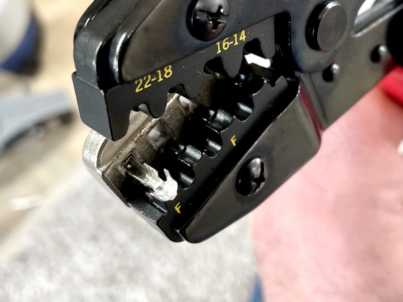
The terminal pins fit into a locking collar, preventing rotation during the crimp.
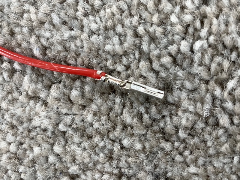
I had bought some spare cheaper pins on which to practice (the VPX supply gold plated versions), and I used these to practice crimping skills.

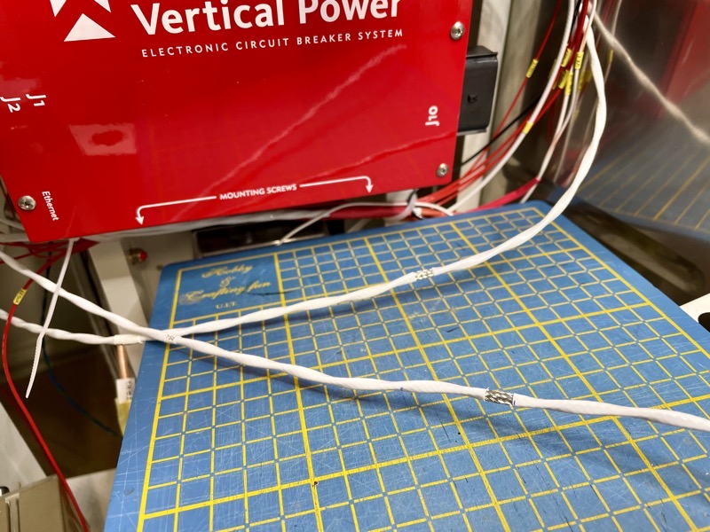
Molex specify minimum pull forces for a satisfactory crimp, so I clamped a crimped pin into the vice …
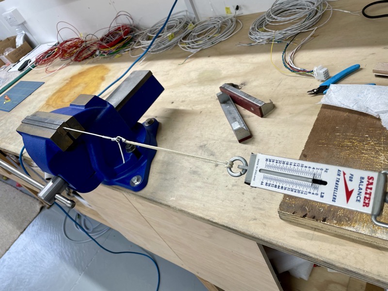
… and used an old spring balance to do a test pull.
18g wire needed to survive a 20 lbs pull, and I gave up when I ran out of puff at 25 lbs.
After a quick happy dance I pressed on with the job : )
This is where the time spent preparing wiring diagrams pays off, since you’ve already planned wire specs.
Working with the fuselage on its side in the rotisserie also made it much more user-friendly, making it easier to prepare the wires.

The lighting circuits employ screened wire, using the screen as an earth return, so these took a while to prepare.

I used Dymo Heat Shrink labels to mark each wire as per the diagrams.

I still have to work out how each power supply wire is to be routed to its respective equipment, but for the moment I’ve stuck them in the approximate location.
I’ll try to use existing holes wherever possible, but I will no doubt have to drill extra holes to produce a tidy harness.
The wiring workstation! I have a Desk Mounted Magnifying LED Lamp which has been very useful.


