


Wiring and Panel – nearly there!
All the avionics connections are now complete, so the last couple of weeks have been spent installing the switches and related wiring.
PFD, Standby G5, pitot, static & AOA connections.
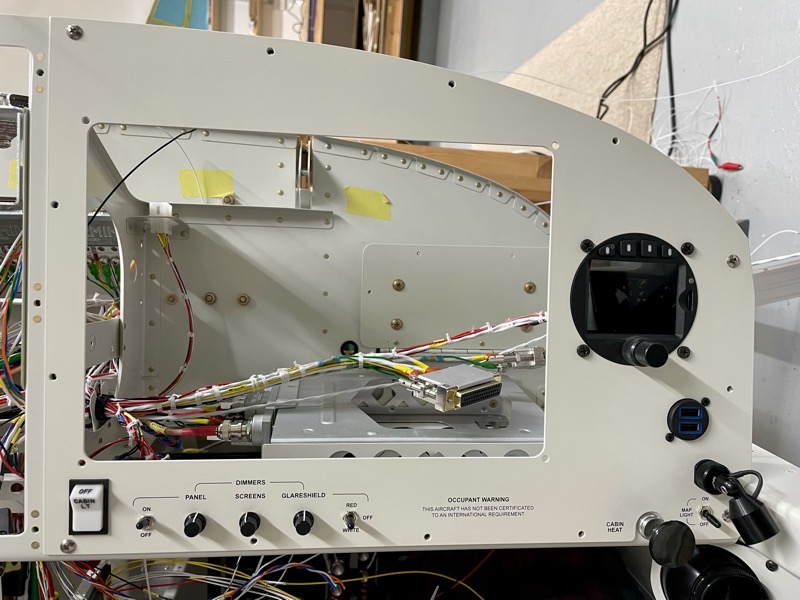
Dimmers, switches, Air Traffic display, USB, Oplite Map light installed in right panel.

Dimmer wiring behind the right panel.
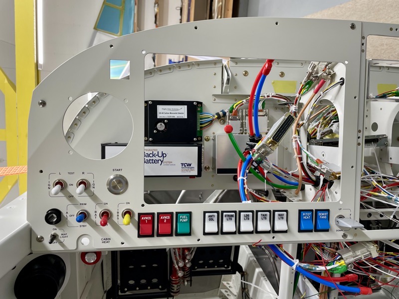
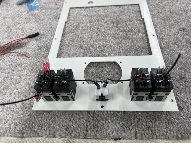
Left panel switches installed.

The Honeywell AML 34 switches are lighted, hence lots of switch connections!

The AML 34 switches use Faston connectors, and I crimped as many as possible on the bench having first worked out the best wire lengths.
The Honeywell toggle switches have screw connections, using ring terminals.
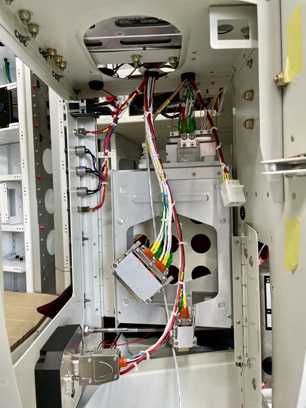
Wiring the centre panel, including the TOGA pushbutton.

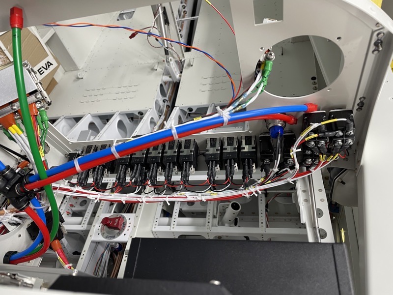
This shows the wire routings at the bottom of the centre stack.
I need to allow an easy route for the OAT probe wire and right wing Roll Servo CanBus … this is because I’m attempting to route these with no wing root connector.
Obviously I won’t be able to connect these until the wings are attached.
Doing this is undoubtedly not essential, since many are flying with wing root connections for these items.
But manufacturer advice is to avoid connections on these data links if possible.
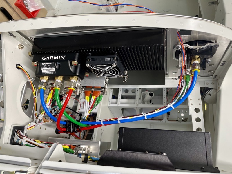
The OAT wire will go to the GSU25 ADHARS on the back of the PFD, and the Roll Servo CanBus will go to the MFD CanBus node.
This is the rear of the right panel, showing the Garmin GTX 45R transponder tray and connections to the MFD.
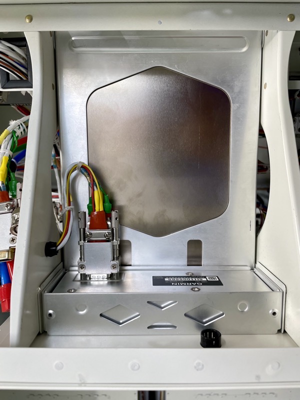
This is the Garmin GMC 507 Autopilot Controller, at the top of the centre stack.

These are the wires that so far need to penetrate the firewall.
There will be lots more when the engine sensor wires are connected to the Garmin GEA24 Engine Monitor.
I’ve positioned this under the top skin access panels, so I can wire this unit relatively easily when the fuselage is off the rotisserie and on its wheels with the engine installed.
Next Jobs
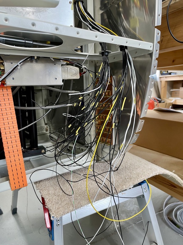
I’ve run all the ground wires up to the “Forest of Tabs” on the rear firewall, so the next jobs include connecting these …

… and also wiring the lower centre panel switches and lights.
I did a test fit of the centre stack components … v happy : )
The tolerance on the required panel cutout and the unit bezels are extremely small, but the care I took with these measurements has paid off.


4 comments on Wiring and Panel – nearly there!
Wow Steve, I think the 380 was less complicated!
Marginally! But the wire looms in a 380 are the size of tree trunks!
Steve, does your control stick hit the flap switch at all?
Hi Logan … no it just misses. I’ve fitted a Tosten Military Style Grip.