


Power Up!
The time finally arrived when I couldn’t think of any more wires to fit … and I ran out of excuses not to switch it all on!
I made a checklist … eg all components and cockpit switches off, controls free in case the GSA28 servos jerked, unconnected power wires in front of the firewall insulated, power supply fused and grounded to Ground Block Stud etc.
I also had a fire extinguisher close by … not that I wasn’t confidant off course : )
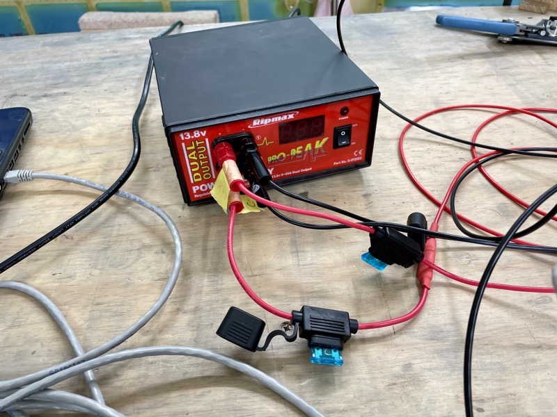
My power supply is rated at 13.8V, 20A with two outputs. These outputs were perfect for me to connect to Bus C and the VPX via fused leads.
Since the Vertical Power PPS system is yet to be fitted on the firewall, I made the connections direct to the Bus C busbar and the VPX power input.

I clipped on the power supply ground leads to the Grounding Block Brass bolt forward of the firewall.
Power Up – Step by Step

The schematic shown here shows the overall system (click to download the PDF).
I decided to test Bus C first … most services connected to this can be individually turned off, enabling a gradual approach!
Then the VPX needed to be configured … involving a power up with all connected items effectively disabled. Vertical Power provide an online configurator which is used to organise and plan the various connections. Then a file is exported into a Windows application, which is used to download the configuration into the VPX itself via a temporary Ethernet connection. This worked very well, with very few amendments required as the configuration is carefully checked in the VPX itself using the Windows application.
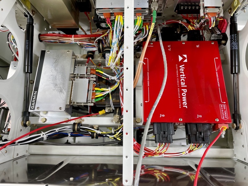
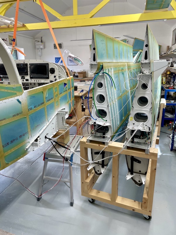
Here are the power supply leads running to the VPX and Bus C.
Once the VPX was ready to go, configured as planned, I switched on items one by one.

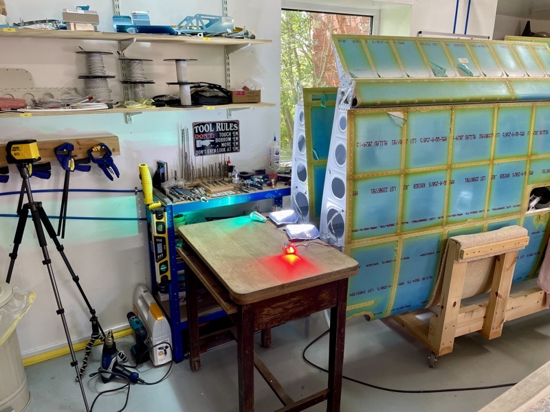
First sign of life!
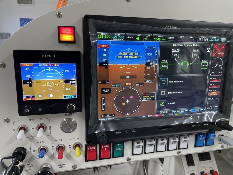
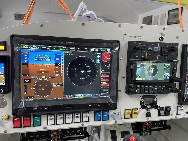
More switches on now … the G3X screen is displaying the VPX electrical schematic.
Individual items can be turned off by unticking the relevant checkbox, replicating a CB. It also shows how much current is being drawn by components.
Testing Systems – Temporary Connections
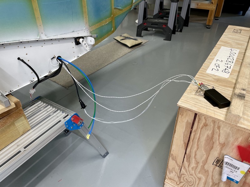
I had to make temporary harnesses to connect up the magnetometer …
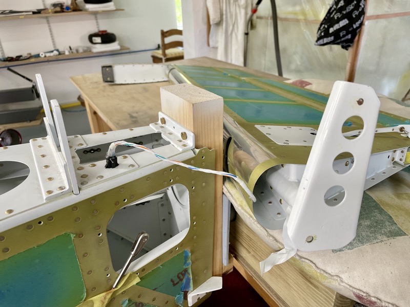
… the elevator trim servo and tail light …
… wing services …
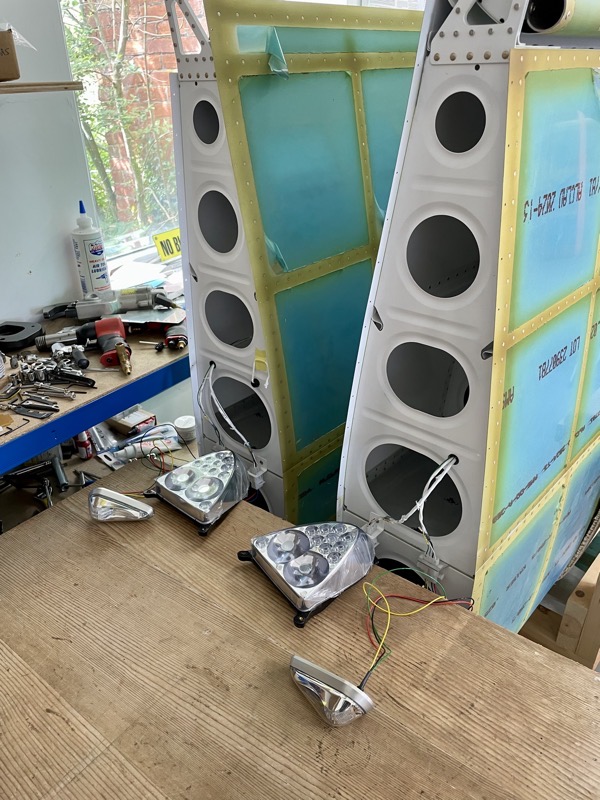
… wing lights …

… and the roll trim servo.
Strobe light test.

Anti-col synchronised with the tail strobe.
Nav lights and Landing Lights.
Testing Data Connections
I didn’t want to spend ages at this stage setting up the G3X system, but I needed configure the various data connections, RS232 and Arinc, in order to see if everything was connected correctly.
In other words to check I hadn’t inserted a wire into the wrong connector pin!
All the meticulous checking paid off, because amazingly everything worked.
I did have to change a couple of connections … the Garmin installation manual implied an ethernet connection to the GTN650 from the GTX45R Transponder was an option, but when I was having trouble getting the GTX to “see” the GTN & called tech support, it materialised that this was intended for a standalone installation without a G3X! It would have been nice to have that written in the manual. Anyway, a day later I had installed the required RS232 link instead, and all was well.
Also the Trig TY91 standby radio only required one RS232 connection to the PFD (or MFD) rather than the two I had installed. When planning this the Trig tech people weren’t sure if a RS232 was needed to the MFD and PFD for control from each side, so I had installed both. In the event both connected caused confusion, and merely disabling one side’s RS232 didn’t solve it … the only way was to remove the pins from MFD connector.
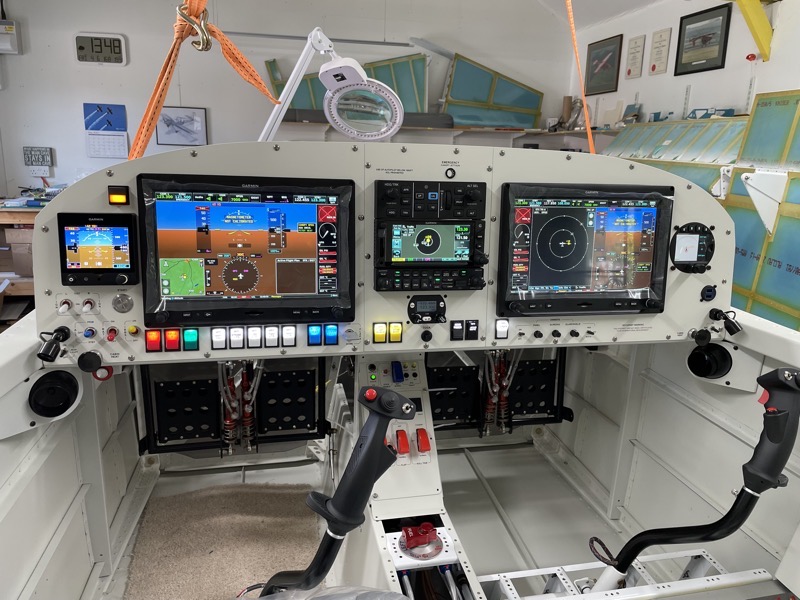
This picture shows a test FLARM traffic output from the installed Air Avionics AT1 Traffic receiver on the G3X and GTN.
I spent about a week testing all the various items … I wanted to ensure wiring doesn’t need to be changed prior to fitting the forward top skin.
It’s with a sense of relief I’m able to put the wire crimpers away for a while!
Another Happy Dance : )


3 comments on Power Up!
Awesome Steve! Your patience and attention to detail is amazing and you have a beautiful aircraft.
Awesome, just awesome!
Congratulations Steve. Lovely work.