


46B-10 to 12 Gear Leg Fairings
We are going to fit 6.00-6″ wheels & hence larger spats, hoping to increase ground clearance & improve operational robustness on grass strips.
Section 46B actually begins with fabricating the spats, but as I’m waiting for the Sky Design Engineering spats to arrive from the US, I thought I’d press on with the Gear Leg Fairings.
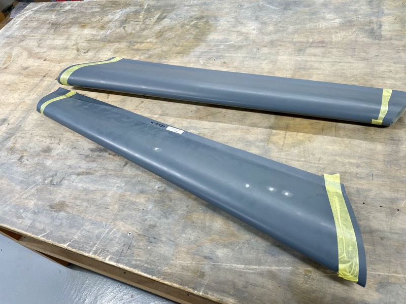
The first job is to trim the ends, marked by scribe lines in the moldings.
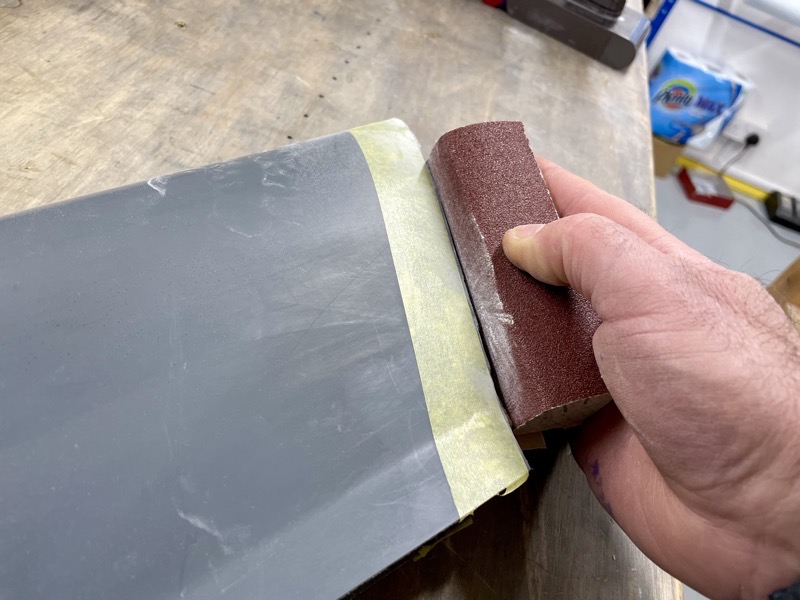
After trimming close to the lines with the Dremel disc, the usual fine tuning with sandpaper.
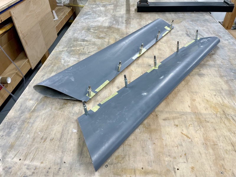
The fairing trailing edges will be secured together by hinges … with a removable pin so that they can be prised open when attaching/removing from the gear legs.
Because the trailing edges are not yet joined, their fit together must first be longitudinally adjusted so that the fairings are not twisted.
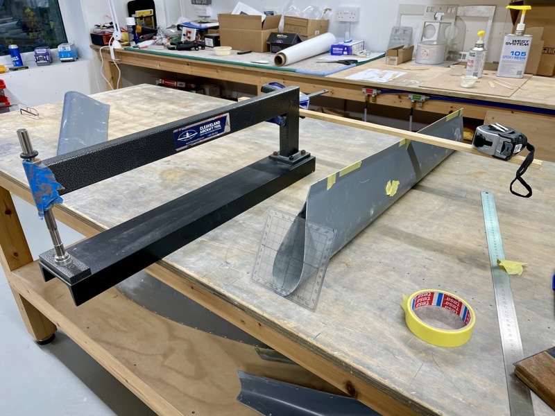
Then manual showed a picture of a C-Frame being used to position the fairings on their leading edges. Seemed a good plan, so I followed suit …
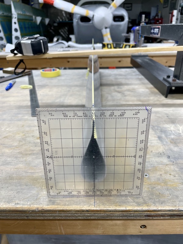
… and then used a square to align the two ends.
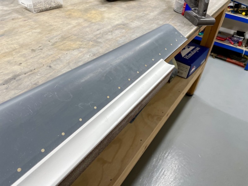
Once square, the trailing edges are taped in postion, holes drilled, and then clecos can be inserted to lock the alignment when required.
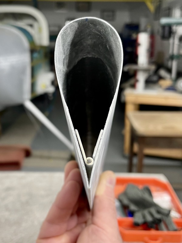
You then place hinges into the trailing edge (TE) V, marking the location.
The idea is to place the hinges such that the TE’s will be held together with a slight pressure.
Obviously it’s pretty critical to get this right, otherwise you risk an annoying gap at the fairing TE’s.
I decided to mark a position slightly above the hinges’ natural resting position (approx 1/32″), hoping to ensure a slight closing pressure.
Now this is where the manual didn’t have a good idea! The steps have been written assuming you have fairings without any grey gel coat, so you can see marks on the hinges to match drill … hmmm?
After some more head scratching I came up with a plan:
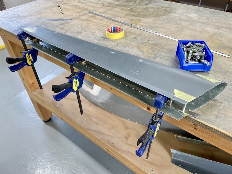
I drilled the rivet holes in a hinge half first, and then clamped the hinge and fairing on the edge of the workbench, ensuring they were carefully aligned with the position marks. The clamps were really effective in locking it all in position.

I then used a long #40 drill to match drill into the fairing.
This does mean accepting lots of holes in your bench, in order to allow clecos!
Once one hinge half is fixed, the second half is easier and can follow the Vans manual steps … but because of the gel coat, you will need to mark out the rivet holes on the fairing rather than the hinge.

Be careful as you drill, since it’s easy to let the drill impact the opposite hinge half due to the small gap … guess how I know!

The rivet holes are countersunk using the hinges to guide the countersink cutter, and keep it from elongating the holes in the fairing.

As usual, lots of holes.
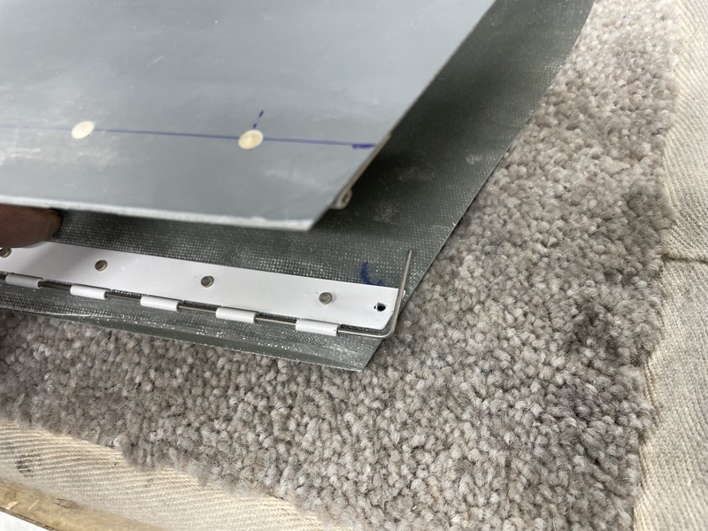
With bated breath I temporarily inserted the hinge pins at this point to check that the TE’s were nicely closed up … success.

After priming/painting the hinges, a squeezer soon sets the rivets.
A long sanding block made trimming the TE flanges nice & straight easy.
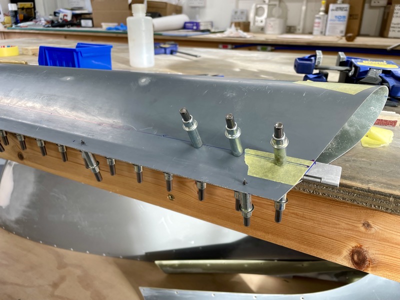
The manual advises a 1″ bend for the upper end of the pins.

I also trimmed a little off the other end of each pin so it didn’t protrude as far from the bottom.
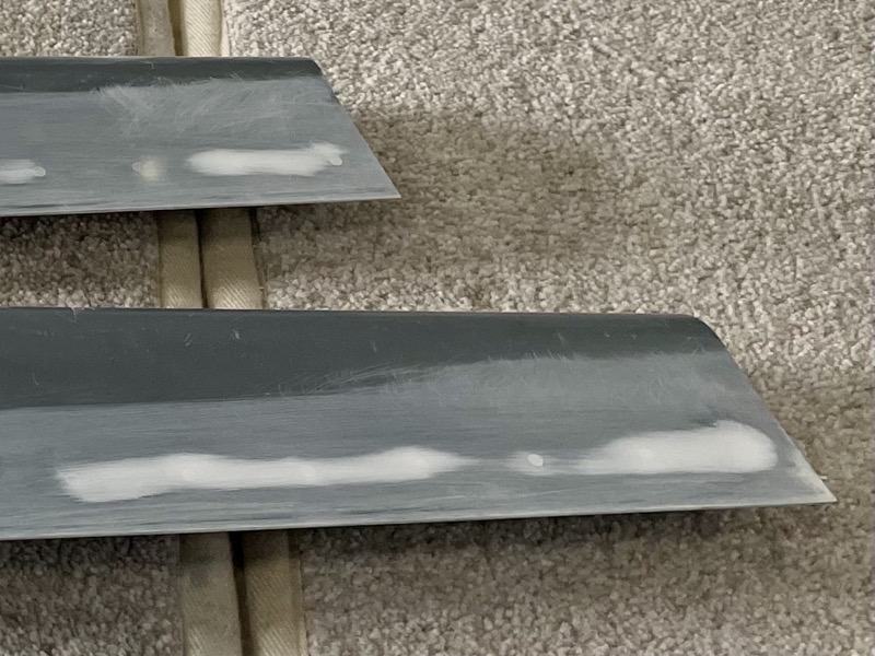
I used small amounts of filler to hide any undulations along the rivet line.
The leg fairings have turned out just fine, so the next task is to trim and fit the Upper Intersection Fairings.


One comment on 46B-10 to 12 Gear Leg Fairings
Gorgeous as always Steve. Congrats.