47 – Cowl Baffle Part 1

After all the dusty composite work over the last few weeks, I almost enjoyed getting back to deburring : )
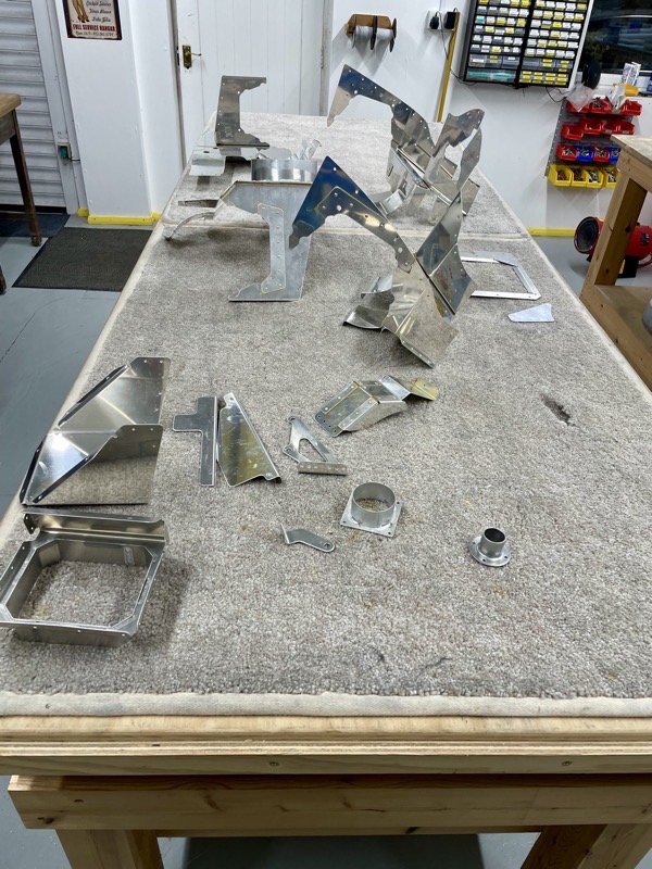
There are a lot of parts that make up the engine baffle, and I’m really grateful that Vans have done all the hard work in producing the intricate shapes which hug the engine.
I deburred all the parts first, and then dimpled/match drilled etc according to the manual.
After clecoing together the components, I test fitted them to the engine. Amazingly the only area which needed a trim to ensure a fit was the CB-00011 Left Fwd Baffle, where it mates to the engine behind the propeller governor.

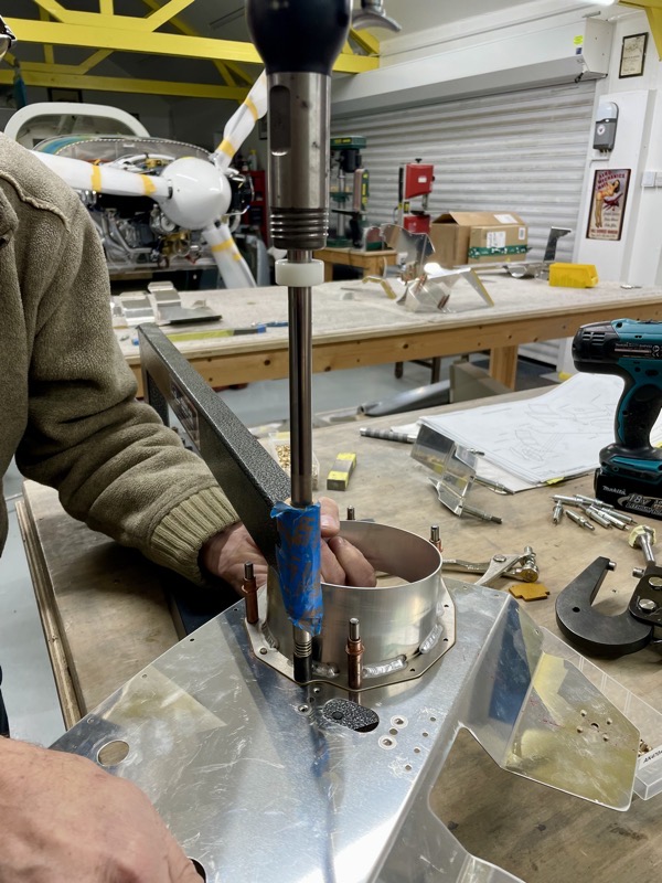
But there is a composite component to trim … the CB-00020 Air Filter Frame.
The Dremel cutting disk easily did the job, but the dust returned!
Actually, where possible I’ve been doing all the composite trimming/sanding in my spray booth enclosure. This keeps the dust away from the rest of the workshop.
Of course there is a vacuuming job to do before any spraying!
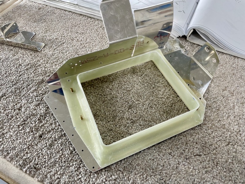
Once trimmed and sanded to the scribe lines, the Air Filter Frame is match drilled with the CB-00009 Left Air Ramp.
As an aside, I’ve noticed this manual section is slightly harder to absorb. In the rest of the manual whenever a part is described it includes the part number. For some reason, in this section they mention the number once and then only the part description thereafter. It’s just needs a bit of back pedalling to remember which part is the “Left Air Ramp” or “Air Filter Frame” etc.
But overall the manual for this kit is fantastic.
So how to finish the baffle?
Leave bare metal, spray with high temp paint?
We decided to get it powder coated since our chap had made such a good job of the instrument panel : )
Rather than deliver a box of small parts to the poor man, we riveted together the four main sections.
So I primed the areas which will be hidden by the various joints.
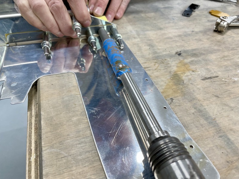
The baffle assembly proved a good riveting workout, needing most of the techniques utilised over the build.
The CB-00037 5″ Flanged Duct is attached with AN470AD4’s, and the C-Frame proved useful again during back riveting.

Due to the duct’s angled tube, one of the rivets couldn’t be set with the C Frame … luckily the squeezer could reach that one …

… and another one needed the angled face of a bucking bar.
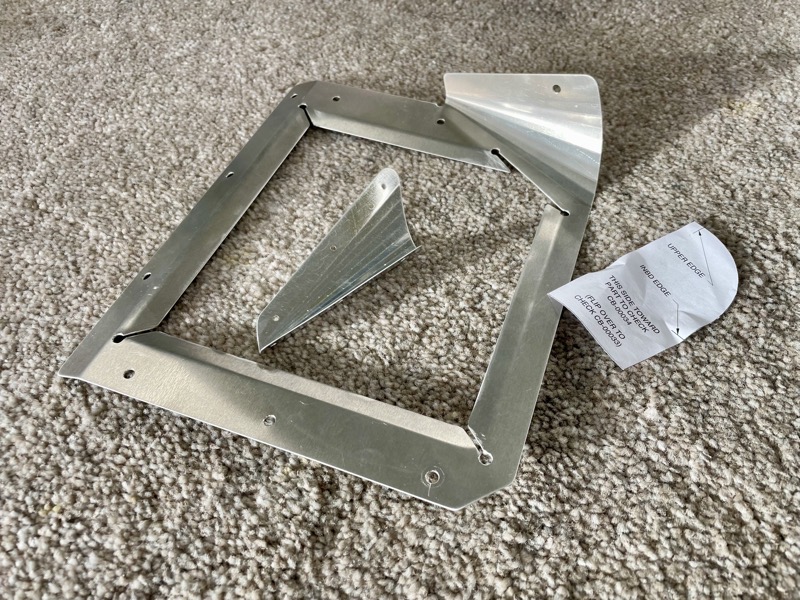
The CB-00033 Air Filter Frame Cover and the CB-00034 Right Air Ramp Cone have to have a cone formed, which mates with the vertical edges of the side baffles to form a streamlined outer edge.
This bit does come later on in the manual, after the baffle is finally attached to the engine. But since I wanted these items to be included in the powder coating, I leapt ahead and fabricated these.
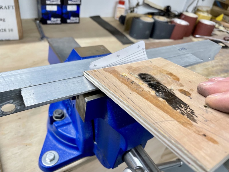
There are templates in the manual which can be printed out at the correct size, and then temporarily attached to the workpieces to act as a bending guide.
Vans suggest a practice on a piece of similar thickness aluminium, which sounded like a top idea, so I did!
I placed some aluminium angle in the vice to provide a sharp, clean edge. Having carefully positioned the workpieces along the template bend lines, & then hitting with a hammer via the suggested plywood seemed to work well.
After the clean bends have been accomplished, a bit of fine tuning by hand soon gets the correct profile.
As with many tasks in this build, it proved easier than expected.
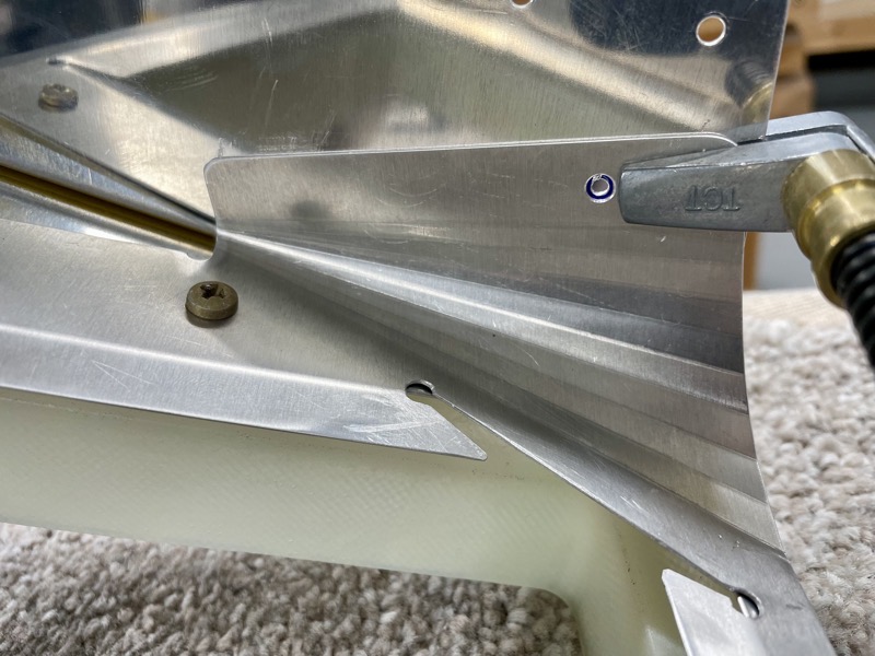
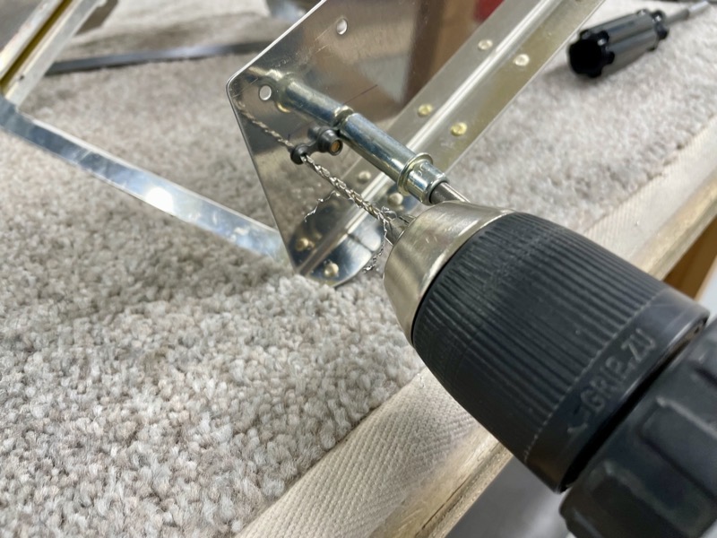
The CB-00033 Air Filter Frame Cover cone has a #19 hole which is match drilled into the CB-00001 Cylinder 2 Baffle.
Since I was doing this before the baffle was attached to the engine, I was careful to make sure the geometry was correct.
Then a nutplate is located and its attachment holes match drilled.
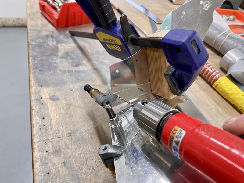
Similarly, the CB-00034 Right Air Ramp Cone is match drilled, and the holes dimpled.
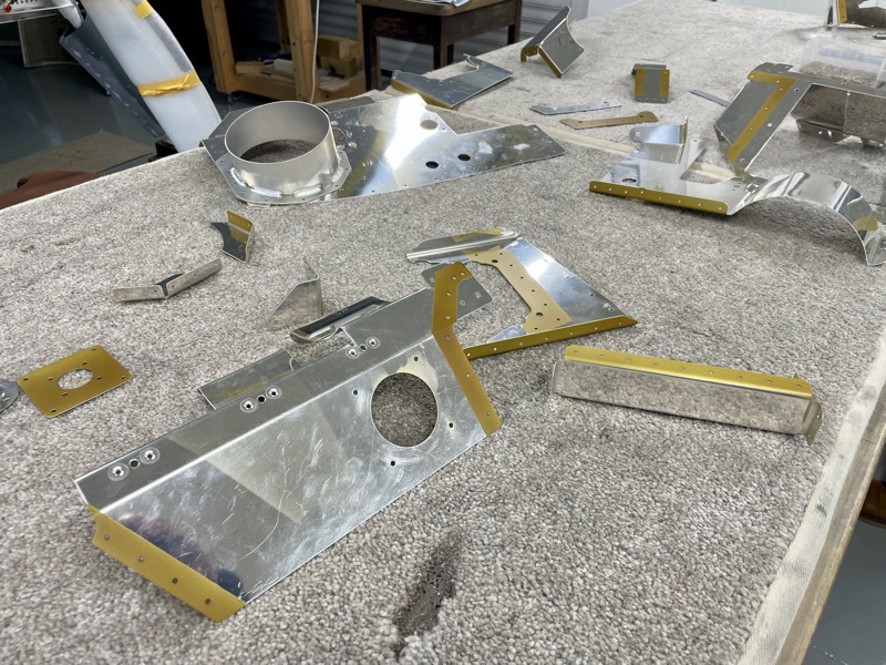
Here are the collection of parts and assembled components ready for powder coating.
So I jumped in the car and delivered them … they’ll be back next week ready for final assembly.
See Part 2 …