


51 Firewall Forward – Engine Wiring
The Firewall Forward wiring has been quite challenging … if you enjoy puzzles then this stage will be right up your street!
It takes considerable thought to come up with an overall plan that routes the various wires efficiently, whilst keeping them safely away from oil/fuel pipes, and with robust separation to avoid chaffing etc.
In my experience looking at engine installation pictures can be very confusing … each one is unique, and the aspect you are particularly interested in is normally hidden by a pipe or bit of engine mount! So what follows will be an overview together with a few of my thoughts.
EGT & CHT Sensors

With a blank canvas you have to start somewhere, so I chose the EGT/CHT sensor wiring.
The first decision is how to join the sensor wires to the aircraft wiring … I chose to use Omega SMPW-CC Series connectors.
Sensor thermocouple wires will normally be Type K or Type J. You have to purchase the correct connector type to match the type of sensor wire you intend to connect. This is because the compensating alloy used in the connector matches the alloy used in the sensor wire.
The Type K connectors are yellow, and Type J are black.
I left the sensor wires undisturbed, just cutting off the spade connectors to allow fitting the Omega’s.
This shows EGT wiring on the right side …

… and on the left.

Having decided where to anchor the connectors, the next stage is to cut (gulp!) the aircraft wires to match.
I found it easiest to pre-form loops in the wires to help …

… with locating in the connector screw terminals.
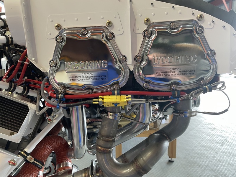
P Mag Ignition Harness

The P Mag ignition harness wires have to be kept separated due to inductance issues.
A tie wrap combined with a short length of flexible silicone tubing does the job.

The P Mag auto harness comes with one long, two medium and one short lead.
So this puzzle involves coming up with the best routing for each side to best suit the available lengths.
Here was my solution, based on how we had orientated the P Mags on the back of the engine.

Right side routing.

Left side routing.
Wire/Hose Routing

I decided to avoid tie wraps on the engine mount, and to use Adel Clamps.
These are difficult to attach, since they want to spring apart etc.
I am very pleased I purchased an Adel Clamp Installer, since this made it slightly less onerous.
It’s hard to predict the number and size of Adel Clamps needed for the job … hence I could open an Adel Clamp shop with all the unused ones that I bought!

Here is an picture taken from the left side looking across the back of the engine.
I have attempted to keep wiring separated from the fuel/oil pipes.
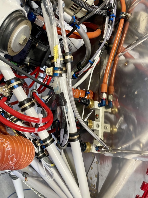
Looking down the left side of the firewall.
And finally the battery side.
I routed the various wires through “Snake Skin” cable sheath wherever possible to keep things tidy.
All the engine wiring is now complete … it was not a 5 minute job!


3 comments on 51 Firewall Forward – Engine Wiring
As always beautiful. I really look forward to coming up to see it in flesh!
Was the Vertical Power PPS able to stay where you put it in September 21? Any comments about routing the wires for the PPS?
Hi Robert
Yes it has stayed in the position depicted on my blog. I have routed the wires from the battery/alternators along the Vans route, and moved the oil pressure pipe a bit higher.
I was able to use the original Vans Starter Cable without modification, but had to lengthen the alternator and battery wires. I was able to route the PPS data wires through the left/top firewall penetration which worked well.