EXP119 Cowl Flap
After the wiring adventure, which seemed to last a long time, it was a pleasure to get back to a bit of metal work.
And the EXP119 Cowl Flap proved to be an enjoyable little project.
Vans have incorporated the cowl flap in the EXP119 installation to provide adjustable cooling for the higher powered engine.
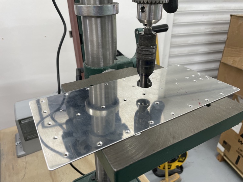
37 Machine Countersinks!

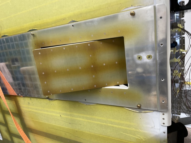
Some match drilling.
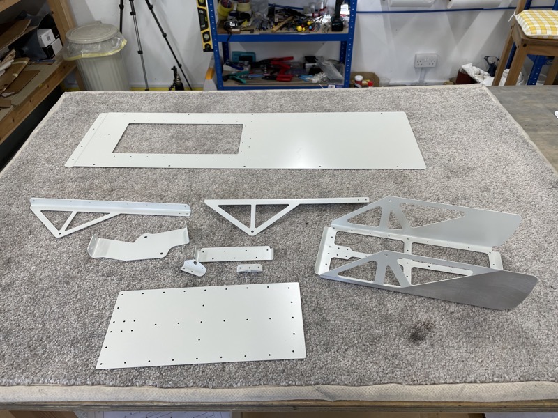
Here are the component parts after the usual deburring, machine countersinking etc and priming/spraying.
I used a 2K paint on the parts for durabilty … I guess they’ll be living in a warm air environment.
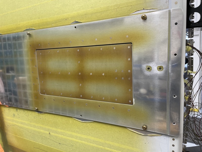
Since I’m retrofitting the EXP119 installation, I had to drill out some rivets either side of the tunnel to allow nut plates to be fitted. These are used to attach the F-14190A Closeout Assembly to the fuselage underside, covering the tunnel.
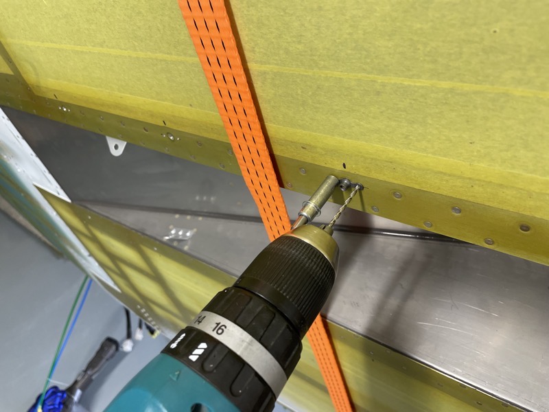
For ease of access I match drilled the nutplate attachment holes from the outside. I used an AN525-8R8 bolt with spacers on the back to grip the nutplate during this process.

Once the nutplate attachment holes are drilled, they need countersinking.

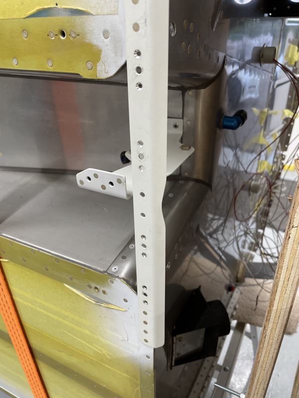
The other retrofit job was to modify the shape of the F-14133-1 Cowl Attach Plates.
Of course you would do this prior to fitting them if you are building the fuselage, knowing you are fitting the EXP119.
I didn’t want to remove them since they were nicely sealed with tank sealant. So I used a Dremel cutting disk and file to produce the adjusted profile.
They have to be modified in order to provide clearance for the twin exhaust pipe exits.

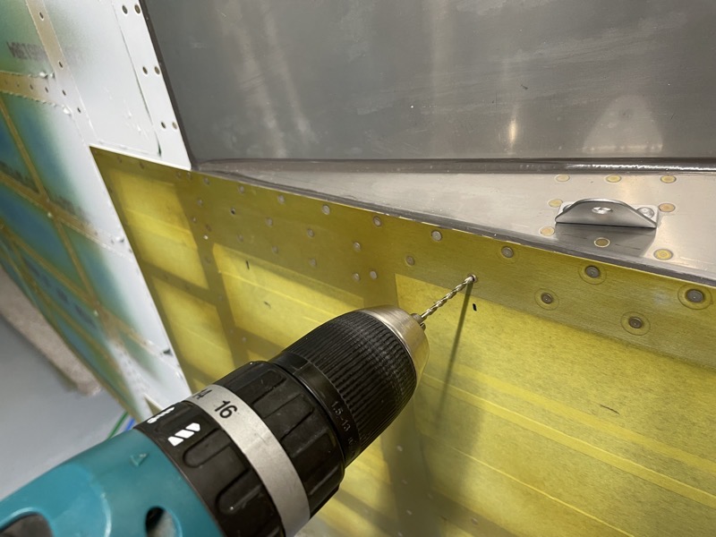
Once the F-14190A Closeout Assembly can be temporarily attached after the nutplates have been installed, holes are match drilled into the F-14132 Tunnel Angle …
… and the nutplate attach rivet holes are drilled in the F-14132, & then machine countersunk flush on the lower side.

I back-riveted the Exit Door Assembly.

And after solving the usual Chinese puzzle of anchoring the workpiece, I used the squeezer on the Closeout Assembly components.
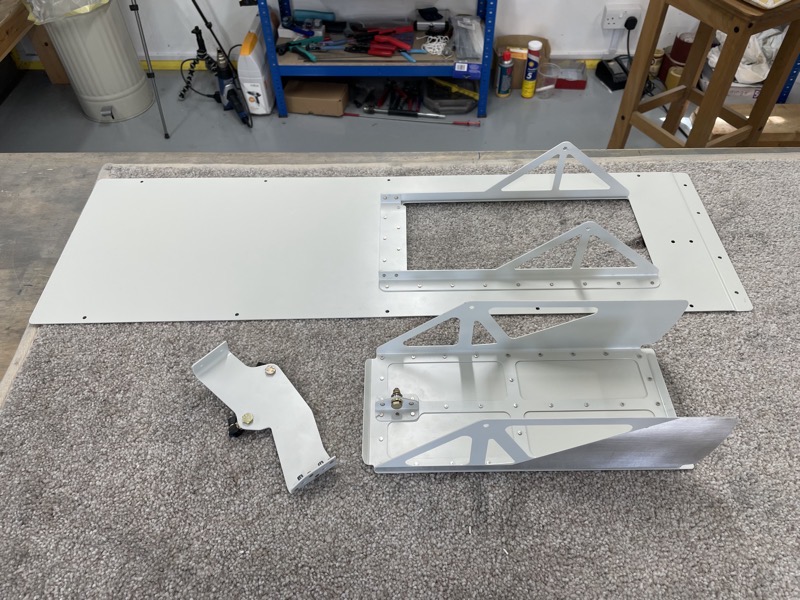
Assembled components.
The hardest job was match drilling the two #30 holes in the Cable Support Assembly to the F-01454 Muffler Shroud Ramp.
I coudn’t work out a way to anchor the Cable Support, so I ended up marking the hole positions and drilling with the support removed. Still not easy since the F-14132 Tunnel Angle is in the blinking way!
Drilling stainless steel accurately is not easy, so I drilled undersize initially in case I needed to slightly adjust the hole positions.
Not easy, but eventually I got two #30 holes in the correct place.
The manual does not mention sealing, but since everything else on the ramp has been sealed with tank sealant, I decided to open the Proseal tin and release the monster! Hence the masking tape.
Thank goodness the manual specifies MSP-42 pop rivets : )

UHMW tape is stuck to the outside of the Exit Door Assembly … I’m not sure why, but I’m guessing to reduce the chance of binding?
Once it was stuck down I trimmed the tape as required.
The manual mentions the usual scuffing/cleaning, so I had left this part of the assembly unpainted. I hadn’t realised that the tape was transparent … if I had I might have considered painting … I’m sure with a good 2K paint the tape would have stuck just fine.
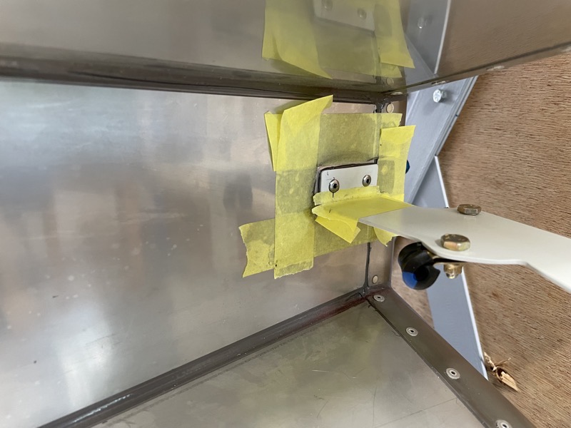
Here is the assembly finished and temporarily attached. It will be permanently installed after the engine control cables are fitted.
Completing this job whilst the fuselage was still on the rotisserie was much easier!