


Wiring – Anti-Collision Light
Once the avionics boxes were installed, it was time to focus on wiring the aeroplane.
Since I’d decided to wire the lighting as per AeroLED’s advice, and also the servos as per Garmin best practice, there was a lot of planning to be done. It’s taken a while!
Wiring Diagram – Left Tailcone

As for the wing wiring, I produced diagrams to specify the wires, connectors and pins.
It’s time consuming, but also serves to get your thoughts straight and work through the options.
Anti Col Beacon

I’d bought an AeroLED Sunbeacon II anti-col some time ago when I was flying to the US.
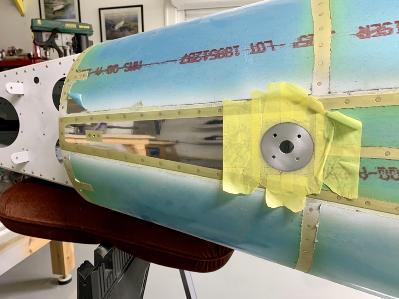
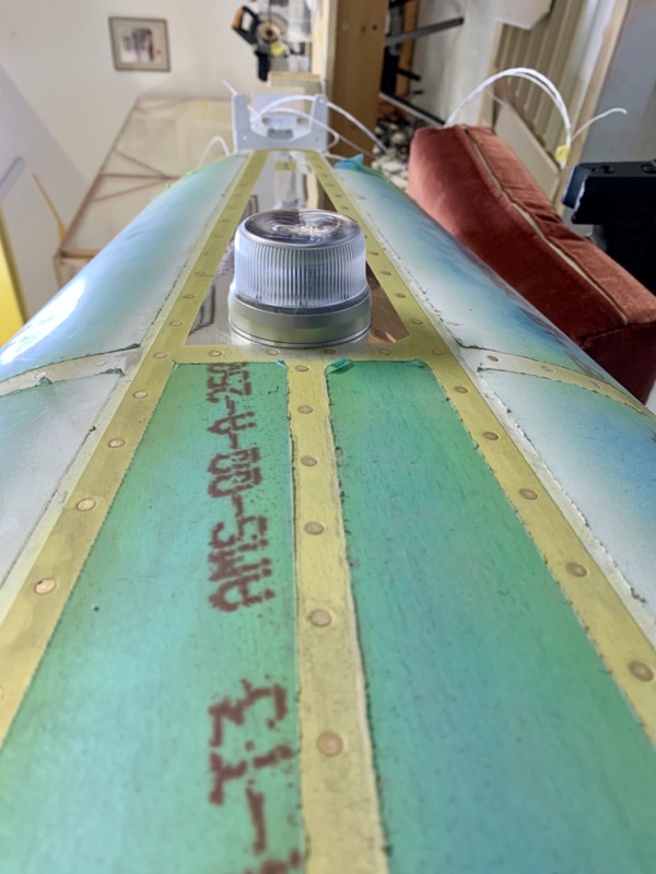
I’d planned ages ago where to site this light, just in front of the tail on the area of top skin without a central rivet line.
This meant I could mount the attachment plate centrally.
In addition I’m hoping it will be low enough relative to the cockpit to avoid distracting flashes on low light days/night.
With heart in my mouth I dusted off the step drill and made the required holes!
I smeared Pro-Seal under the mounting plate to keep out the rain – hence the masking to tame the sticky monster.
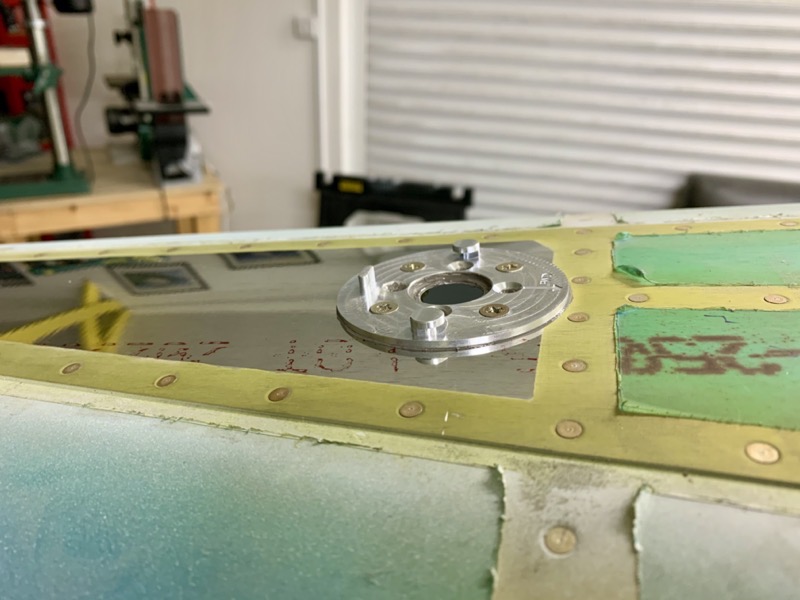
The light neatly locates on the plate, secured with a grub screw.
Interestingly I used some “expired” Pro-seal … it did set, but not as completely as usual. Good enough in this site, but definitely not suitable for important jobs.
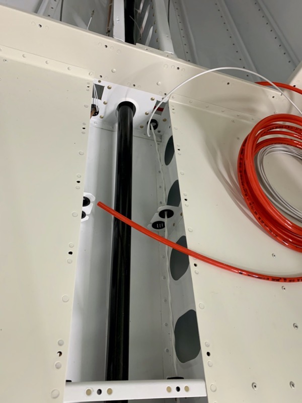
I had already run the 1 Core 18AWG Screened (1C:22S) cable in the tailcone.
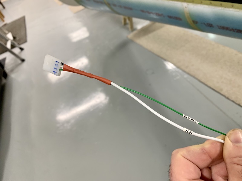
I wired the connectors, using Molex 0.062 pins.
I used a solder sleeve to extend the cable screen to the earth return.

The light has a “Sync” wire. I’m not sure if I want the beacon flashing in unison with the strobes, but I decided to wire in this cable anyway.
But in case I want to stop the sync, I added a DSub connector covered by heat shrink tube, providing an easy way to non-destructively break the connection.

Once the beacon is permanently attached after painting, I’ll secure the connector lead with a cable tie.
I drilled small cable tie holes along the inside edge of the bulkhead to attach the wires.
Cable Ties

Talking of cable ties, I’ve found my Cable Tie Gun very useful in attaching cable ties …
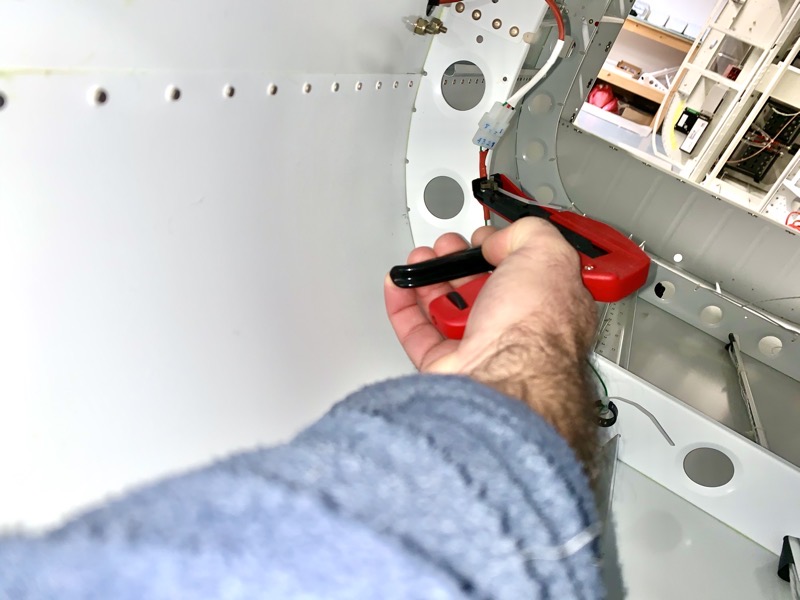
… especially in hard to reach areas!
You can adjust how tight the ties are pulled with the knurled knob at the bottom of the handle. It cuts the tie’s loose end off very close to the grip.
Having checked all the connections, and made sure there were no shorts to earth etc using my multimeter, I couldn’t resist a little test!
I connected up my 13.8V power supply through a 5A fuse … and with bated breath switched on … here’s the result. Another happy dance : )


One comment on Wiring – Anti-Collision Light
It’s looking beautiful Steve, retirement is really suiting the project!