
The avionics wiring continues, and I think I’m just about on my self-imposed schedule to complete it by the end of this month.
Like a lot of aspects of this project, although this phase was very daunting, once started it becomes a lot less intimidating!
Here follows a few comments and pictures to give a “flavour” of the process.
Building a Garmin Connector
Garmin sell “Connector Kits” for each component in their G3X system, which include most of what is needed to make the connectors.
The data wires are typically 2 or 3 core screened cable, and the screens are earthed on the connector.
Here is a connector shell with the supplied screws to attach the screen block … no extra screws are in the bag, so don’t loose any!
Screen attachment block attached.
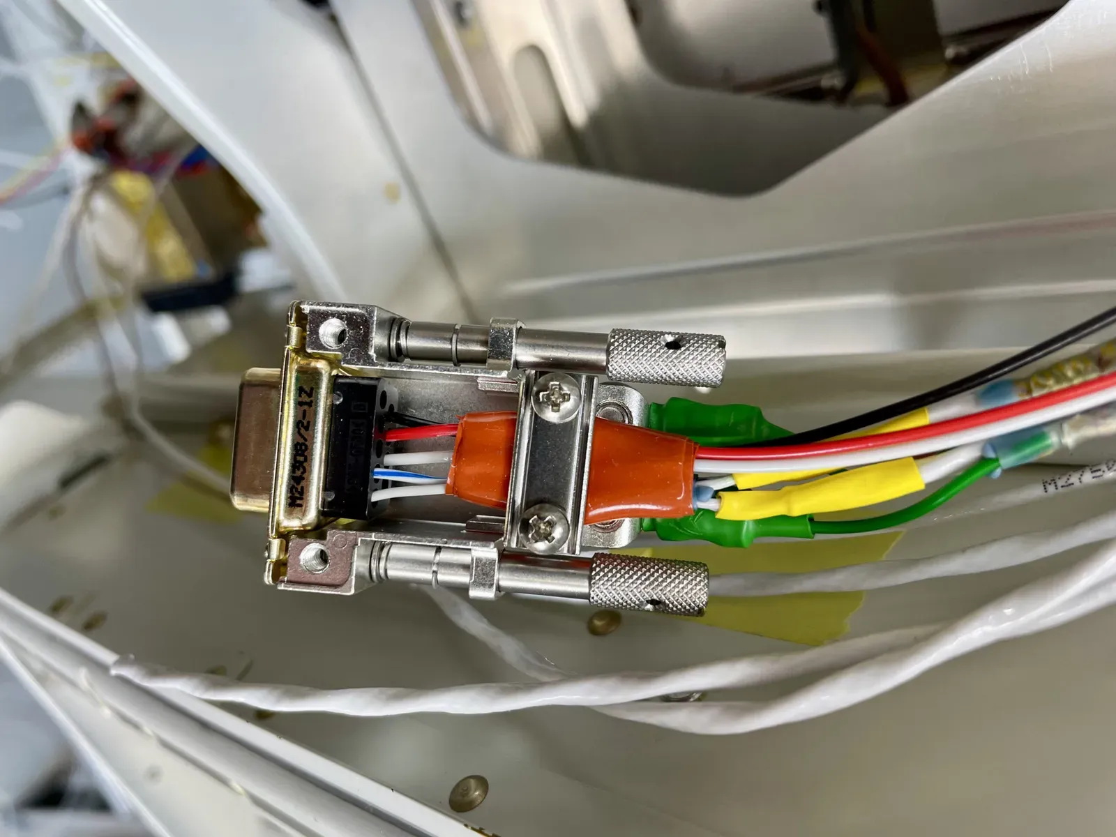
Wherever possible it is easiest to insert wires on the bench. But a lot of the time this isn’t possible, since wires that need to be inserted are already in the plane.
For some reason Garmin do NOT include the required screws/washers to connect the screen ring terminals, so these have to be sourced seperately.
Here are the screen pigtails attached to the screen block.
The G3X installation manual have clear but involved instructions detailing recommended lengths of pigtails etc.
I’ve used the recommended Solder Sleeves to connect the pigtails to the cable screens.
Note the pigtails exit TOWARDS the connector block, with a short, straight run. In the past Garmin stipulated they exit to the rear and curve around, but this has now been changed, since there is much less electromagnetic noise with the short, straight run.

Note that the Garmin Training videos in the " Garmin G3X Wiring Fundamentals Series " has now been updated to reflect the current G3X installation manual.
Once the wires have been inserted, they are protected by self sealing tape before clamping.
I double check all pin numbers before inserting! The pin holes often have very tiny numbers embossed near the holes, but can be hard to see … I’ve found shining an light slightly angled helps to show them up.
Keen eyesight or crisp glasses are needed!
Once happy the connector cover is screwed into place.
For some components the connectors are screwed into a “Backshell Assembly”, so everything connects as the unit is slid into a tray.
This is the one for a GTX45R transponder tray.
Lots of planning has been required to work out how to get the cables to the components.
Here is the GTX45R installed in its tray behind the right instrument panel.
Screen Pigtails
Lots of screen pigtails have had to be fabricated in situ, since the cables have already been attached to their source in the plane.
Following the manual advice concerning dimensions, little windows of screen are exposed.
I’ve found it easiest to fix the pigtail wire in place with tape before sliding the solder sleeves over.
Once in place the connections are soldered with a heat gun.
CO Detector & GAD 29
My CO detector has screw terminals, and I decided yet another P-Clip was needed to secure the wires.
Here is the CO detector and GAD 29 all connected.
Moving onto the actual instrument panel components next! : )