
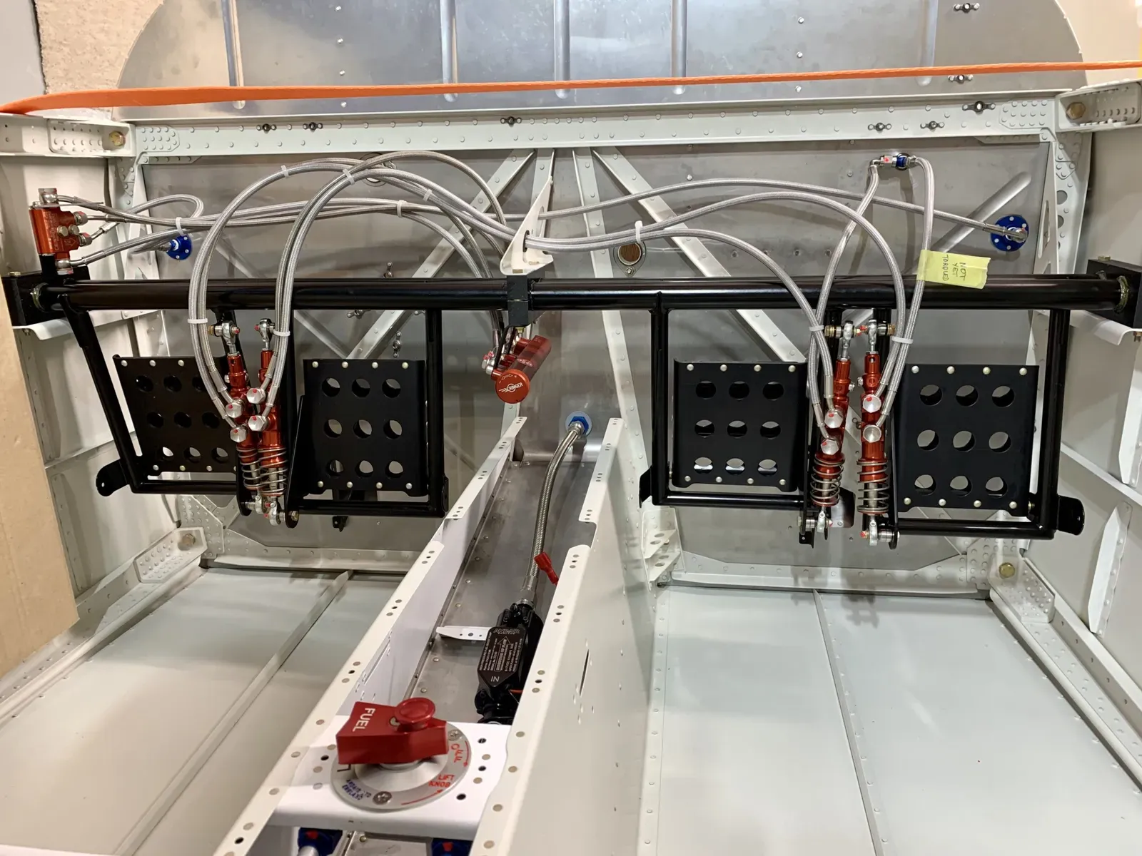
The picture above shows the brake system installed … it took a bit of head scratching to get there!
These are all the parts supplied by Beringer, which are all very nice quality.
The Beringer RV14 manual seems to be based on the RV10, so a lot of part numbers do not relate to the 14. They also have updated some parts, so a few washer callouts etc don’t work.
But with a bit of test assembly and planning it all begins to make sense.
Brake Cylinders
The Brake Cylinders arrived with the eye bolts unassembled, so the first job was to attach these and adjust to a suitable length.
As a first guess I’ve adjusted these to position the brake pedals parallel with the rudder pedal assembly. I’m not sure if this will need adjusting?
I test assembled the L & R pedals to ensure clearances.
Brake Regulator
I decided to fit the Beringer Brake Regulator, which apparently does a good job in balancing brake application L & R to help with keeping straight.
The manual suggests it is attached to the underside of the middle F-6115 Bearing Block, using a supplied bracket.
This seemed like a good plan, since although once adjusted you shouldn’t need to access it very often, in this position it’ll be easy.
The bracket was supplied flat, so I bent the lugs to a suitable angle.
Here it is installed on the bottom of the middle bearing block.
Parking Brake
The parking brake valve is installed on top of the left bearing block, again using a supplied bracket.
Hoses
The Beringer Manual has good diagrams showing how to couple all this up. This is the one relevant for my installation.
I have cheated again and purchased the excellent hoses produced by Tom Swearengen at TS Flightlines and sold by Aircraft Speciality.
Tom has produced a good manual with the hoses … the hose names do not match the Beringer manual, but it doesn’t take too long to sort it out.
Once all the components were in position, it didn’t take long to assemble the hoses.
I decided to position my rudder pedal assembly at the rear position. The hose from the Co-Pilot R pedal up to the reservoir is a little short I think … but I’m not sure on the exact angle of the pedals yet. I’ll know this once the rudder is linked.
I sent Tom an email asking about this, and he replied within minutes (on a Sunday!) … can’t ask more than that. He said he’d make me a longer one if required, but suggested I check it when rigged properly.