


Sky Design Engineering Wheel Spats – Part 2
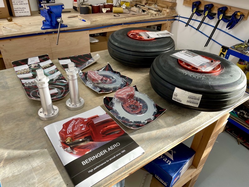
We had a late Christmas present from Beringer … the 6.00×6″ RV14 Wheel Kit arrived.
Nicely packaged and engineered … the axles are specially produced to fit the Sky Design spats.
Their arrival meant I could press on with fitting the spats.

It is obviously much easier to fit the spats to the wheel size off the aeroplane.
But of course you need to be able to mount the spats exactly as they will be once they are actually fitted to the gear leg.
By inserting the axle and ensuring it is correctly located laterally, the brackets can be temporarily installed.
The outer bracket is easily bolted in position.
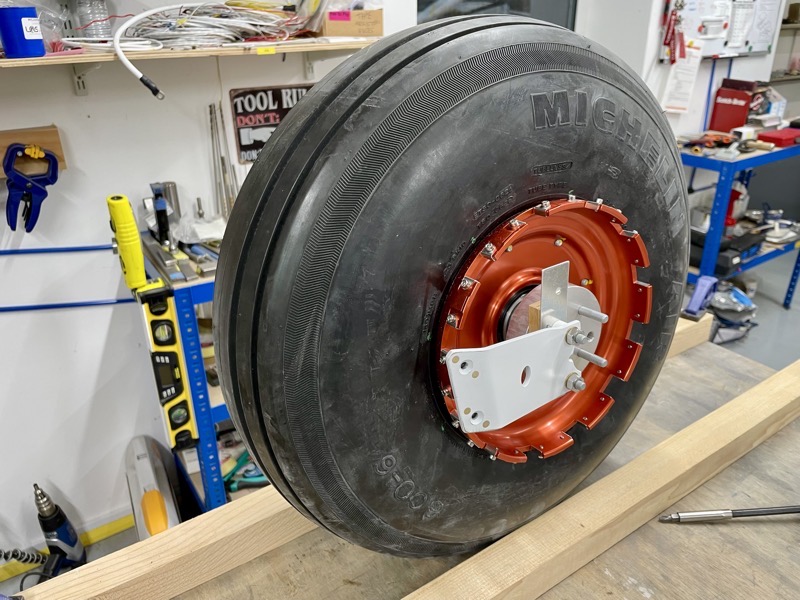
The inner bracket needs a bit more thought, since it will be installed on stand-offs inside the U-01421-L & -R Gear Axle Fittings.

So I made a wooden block and shim to replicate the thickness of the U-01421’s, and then attached the inner spat brackets on the standoffs.
Now it was possible to securely locate the spats on the brackets in their correct positions, in order to be able to trim the wheel holes accurately.

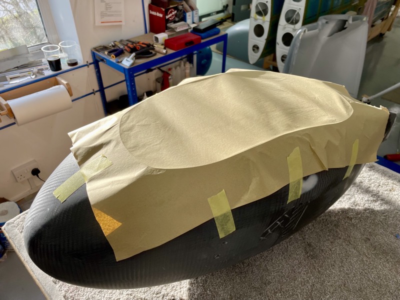
First of all a “best guess” hole has to be cut for the wheel so that the spats can be attached to the brackets. Sky Designs mark a suggested initial hole size, but these were produced for a Matco wheel/brake unit. Although I’m guessing these marks would be fine, I thought it best to measure myself for the Beringer’s with Michelin tyres.
I didn’t want to cut out too much of the precious spats!
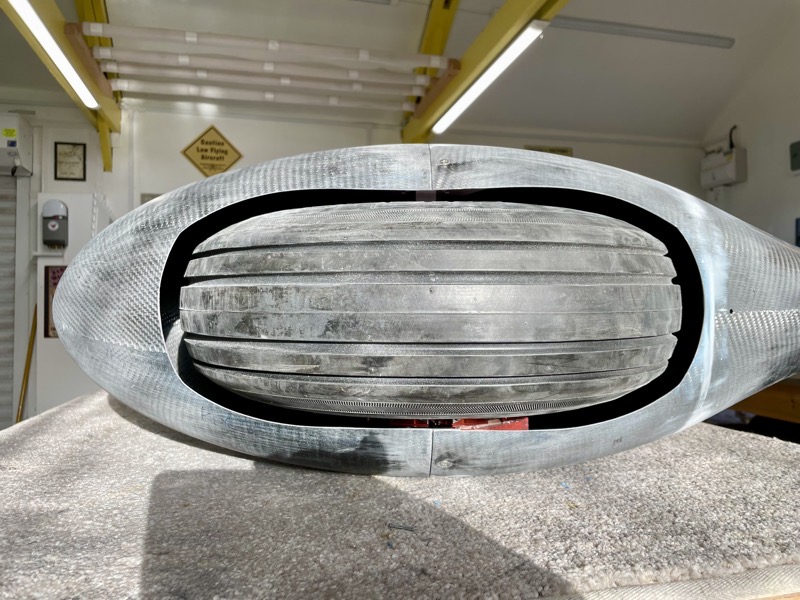
I traced the tyre profile …
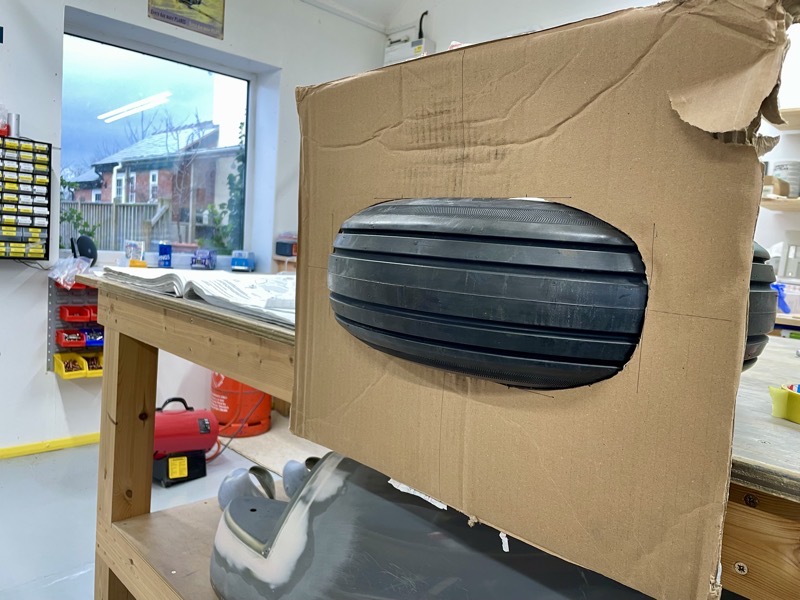
… and having worked out how much tyre would be below the spat, produced a template for an initial hole.
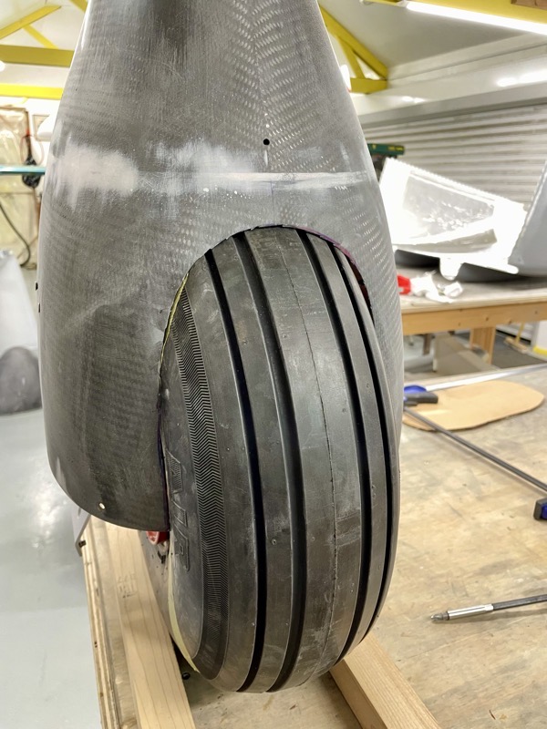
Using this and a few iterative trims, I cut out just enough so that the 410010 Aft Wheel Fairing could be attached to the brackets.
I ended up having to cut out quite a bit more than my template predicted, due to the spat lower curvature.

Since the fwd & aft spat is split on the wheel centreline, I used this initial undersized hole shape as a template for the fwd spat “best guess” cutout.
This was good enough to allow the fwd spat to be attached to the bracket.
And then it was a straightforward task to mark and trim the cutouts to achieve the suggested 5/8″ clearance all around the tyre.
I used the first completed spat cutout to mark the second spat.
I cut undersize, but enough to be able to attach the second side’s fwd/aft spats without the iterative process of the first side.

And then fine tuned for the 5/8″ gap.

The Beringer brake units fit nicely in the spat profile.
The only thing to watch is that the inside lower nutplate is close to the bleed nipple.
Using a shorter screw at this location should maintain adequate clearance.
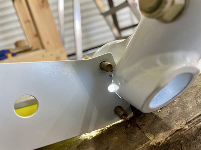
When testing the fit of the 410039 Inbd Wheel Fairing Brackets on the Vans U-01421-L & -R Gear Axle Fittings, I discovered slight interference with the welds.
In order to fit the brackets on the studs they both needed a small trim.
I was initially concerned that this would weaken the bracket attachment due to reduced hole edge distance …
… but having removed the minimum material to be able to fit them, although not ideal, I think it’ll be OK.
I may have had slightly oversized welds on my Vans axle fittings?
See Part 3 here …


One comment on Sky Design Engineering Wheel Spats – Part 2
Beautiful work as always. J