


47 – Cowl Baffle Part 5 – Inlet Seals
During the construction of the baffles, and test fitting the cowling, I realised there was an annoying snag brewing.
Ideally the baffle inlet air ramps should be slightly below the lower edge of the cowling inlet, so that the inlet seals will lie flat.
Of course the engine is likely to sag 1/8″ to 3/16″ inches, so during construction it may be best to accept this error.
But I reckoned my cowling inlet position was about 1/8″ too low, even allowing for some engine sag.
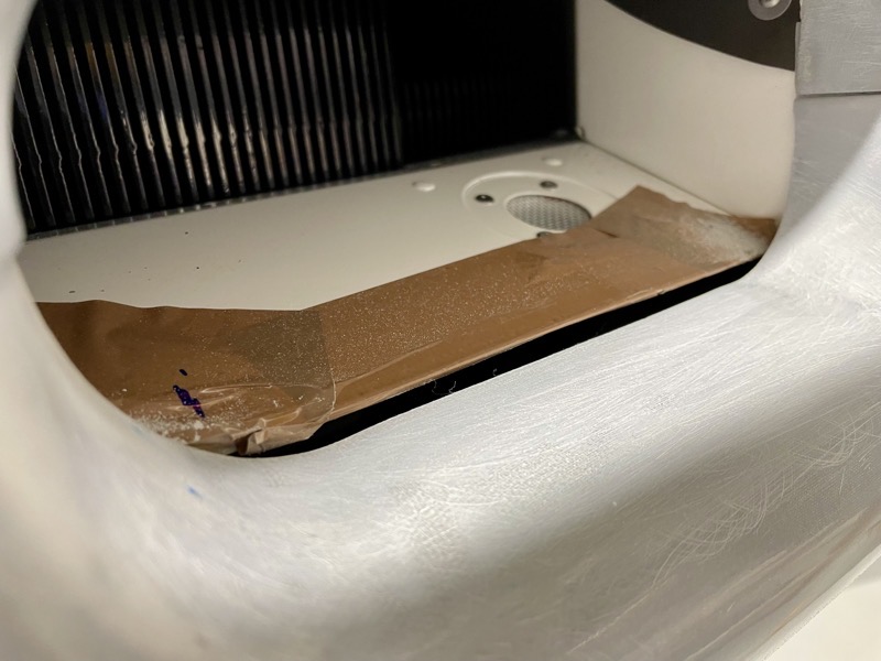
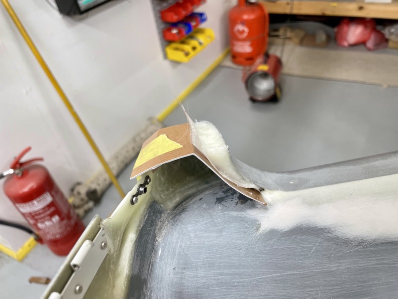
So I made the decision to face the extra work, and raise the cowling inlet lower edges by 1/8″. The picture shows parcel tape added to the right baffle air ramp to act as a release agent for epoxy/flox.

It’s hard to see in this picture, but I made a jig to sit at the correct height above each baffle air ramp, so that the top of the added epoxy/flox would be moulded in the correct vertical position.
I added enough epoxy/flox to shape the inlet, and kept in place with peel ply during the cure.
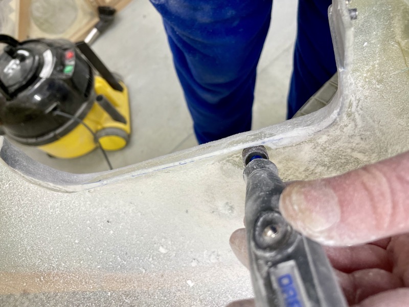
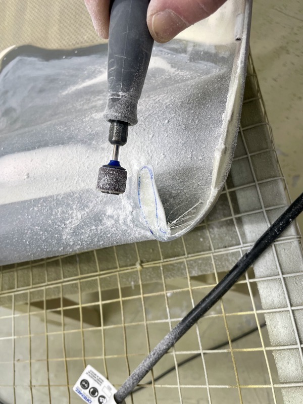
Once set I used the Dremel sanding drum to grind off the lower edges …
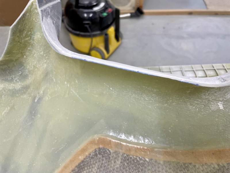
… resulting in a raised lip.

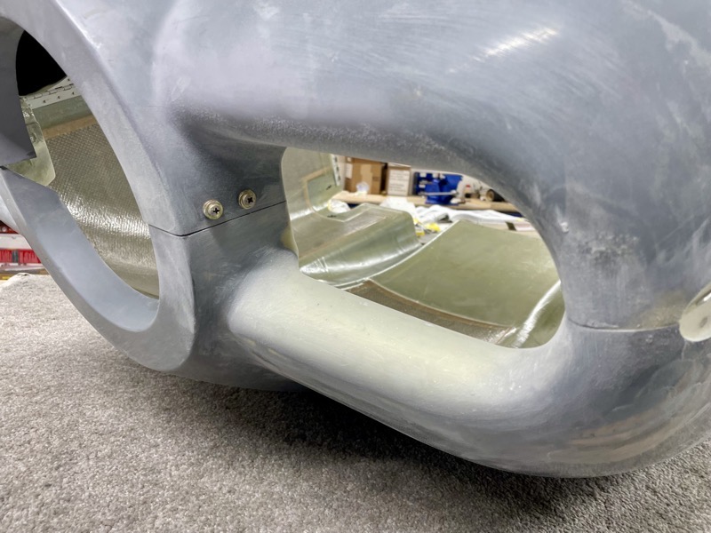
This shows a test fit of the cowling to check the underside of the lower inlet lip was now at the correct height.
I went for a compromise, allowing for some future engine sag.

As per manual 47-25 I measured the misalignment between the bottom cowl air inlets and the CB-00033 Air Filter Frame Cover, CB-00007 Right Air Ramp, and CB-00034 Right Air Ramp Cone.

Since I had ground off the lower edges of the cowling inlets, I added two layers of glass cloth to restore strength.

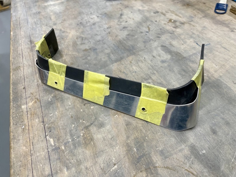
It took quite a while to hand form the CB-00036-L & -R Clamping Strips, and then clamp them in a position to replicate the measured misalignment.
I again used parcel tape on the strips to act as a release agent, which I’ve found to work very well.
The picture shows the epoxy/flox added to the gaps and curing.
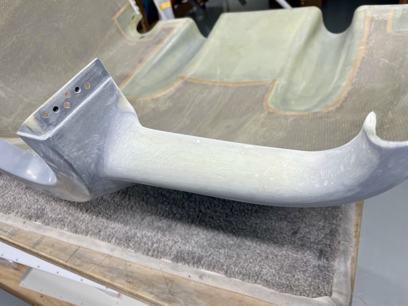
Once set the rear edges and corners of the inlets are aerodynamically shaped, involving yet more dust!
I used the Dremel for rough shaping, and then shaped sanding blocks.
Then the top cowl inlets have to be matched to the bottom cowl inlets.
Having measured etc I ended up using cardboard to mould the epoxy/flox into the approximate shape.
And then after test fitting and marking, more dust!

I used my long sanding block to fine tune the level of the top cowling outer edges … the cardboard made sure I wasn’t changing the carefully finished central area.
I finished the final top/bottom matching with the cowlings connected.
The rubber seals are now aligned with the CB-00036-L & -R Clamping Strips ready for match drilling.
I found it best to tape the seals into position on the strips prior to clamping.

Once happy with the location I used clamps and a wooden block ready for match drilling.

Match drilling parallel to the cowling inlet lip lower surface.

The final result.
Loads of extra work raising the inlet lips, but I suspect it has saved future frustration with both the fitting of the cowling and the look.
I’m not sure why the cowling ended up a smidge too low, since I built as per the manual. The MT Propeller spinner is a very close match to the Vans stock one, but I guess the engine sag allowance is critical. Perhaps I slightly overdid it, although it looks and measures about right?
A few other builders have mentioned the same issue.
We’ll see : )


2 comments on 47 – Cowl Baffle Part 5 – Inlet Seals
Hi Steve,
It seems I have the same issue that you encountered in that the lower cowl lip is too low in relation to the inlet ramps. Your solution looks great, but I am having a hard time envisioning the process. Did you cut out a section of the lower cowl lip first and then set a jig on the inlet ramp that protruded into the void? Filling in and shaping the flox to create the new lower cowl lip and profile?
Was flox sufficient to the task now that you have some hours on the plane? I see that you added some layers of glass to the inside of the lower lip later on which probably added a good deal of integrity to the modification.
For the record I have a friend who built a nose dragger and didn’t have this issue. But my build is the EXP motor on a taildragger, My cowl may be a little low but I did my best to follow the instructions. If the engine does indeed sag an 1/8″ my spinner would be perfectly centered on the cowl. Did you experience any engine sag? I hear some builders say that they did not see any sag. I know that Vans has delivered at least two different rubber isolators for the engine mount which may have an impact on this issue.
Your blog has come to my rescue again, I am very grateful for it and to hear other builders have had this problem.
Thanks for the help.
Dave Romuald
Hi Dave
Sorry you’ve had the same problem! I don’t think it’s anything we’ve done wrong, it’s just one of those things, and we certainly aren’t alone. But it is definitely worth sorting the problem now, and be assured the method I used with flax/tape etc has proved very durable. You would not know now of any issue inspecting STRV’s intakes … but see the seals sitting nicely! : )
The engine has sagged slightly after 130 hours, just shy of 1/8” I reckon.
“Did you cut out a section of the lower cowl lip first …”
No I didn’t. I attached a guide (bit of plywood I think) on the baffles to try and judge how much build up to make, then added flox mix on top of the lips to raise the profile. Once set I then tried to judge if I’d added enough material to to be strong enough once the underside had been ground away. I seem to remember it was a bit of an iterative process.
Then I used the Dremel to grind away underneath, hence raising the lip for the seal. I then decided to add some tape to strengthen, because like you I was unsure of the flox on its own.
But as I say, it’s all proven very robust with no issues after 130 hrs.