


Avionics – Transponder Tray

Well here’s the plan for the GTX 45R Transponder location.
I want to keep it as far forward as possible, to allow room for any required switches underneath the right G3X screen.
The unit slides into a supplied tray enclosure, and is secured by 3 screws each side.
To be able to slide the unit out the whole attachment tray will have to be removable …

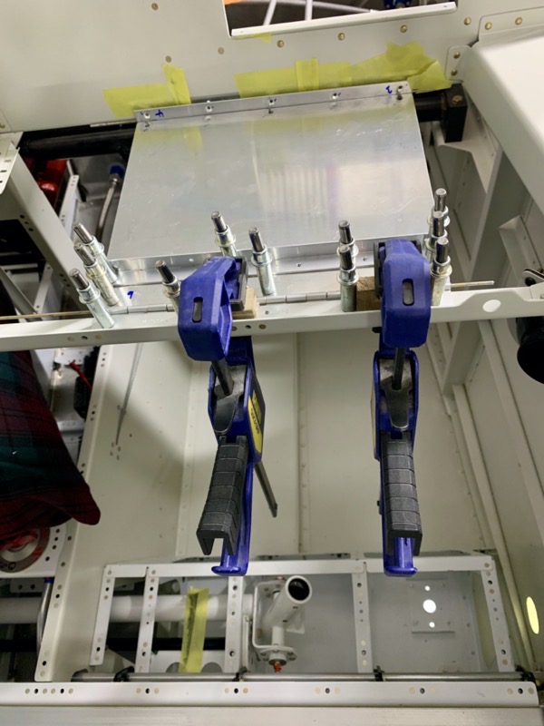
… so I decided to make a tray attached to the intrument panel and sub panel by hinges. By sliding out the hinge pins the whole structure can be removed.
It’s hard to judge how rigid a structure is going to be until built, but I reckoned the GTX 45R supplied tray itself will prevent flexing.
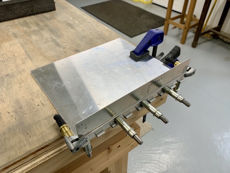
I used 0.032″ Aluminium Sheet, and 1/8″ angle.

The fuselage rotisserie made access to match drill the hinges into the structure much easier.
Match drilling the aft hinges.

Before riveting it all together I made some lightening holes … saved a massive 30g, but I suppose it all helps.
Some wise chap once told me:
“If you plan on putting something in your aeroplane, see if it falls back down when you throw it up in the air … if it does, think carefully if you really need it!“.
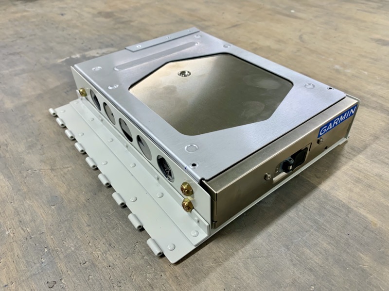
Here’s the complete tray primed and painted.
Having seen how rigid this structure becomes once the unit is in place, I reckon 1/16″ angles would probably be just fine.
I used MS24694-S1 machine screws to attach the Garmin tray to my tray uprights … they needed to be as small in length as possible to fit in the available space at the front. I chose MS21083N08 Nyloc half stiffnuts, ideal with their low profile.
Remove the two hinge pins and it all drops down for removal.
I just need a cunning plan to stop the pins sliding out by themselves!


