12 – Empennage Fairing & Gap Covers Part 1
Gap Covers
After deburring the F-14111 Gap Covers I applied the specified bends.
I made some little templates out of card to get the correct angles.
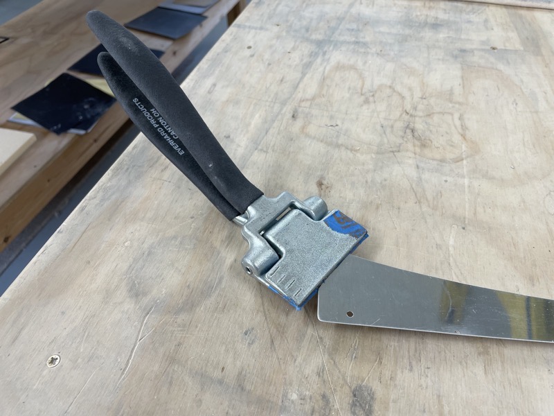
I used a OFFSET HAND SEAMER to bend the small end tabs …
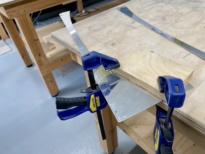
… and clamped the covers between the bench and another wooden block, using another block to form one of the larger bends.
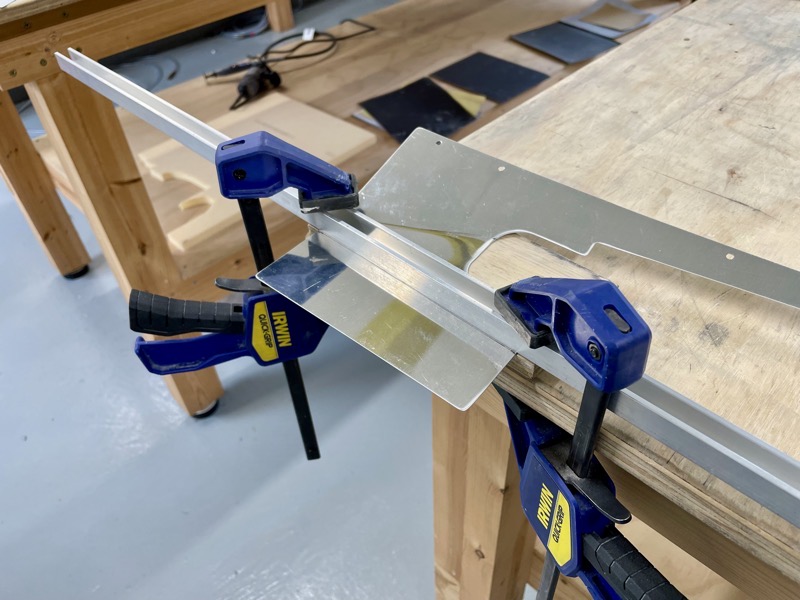
Because of interference with the previous bend, I needed to find something thinner but rigid to clamp the material for the last bend, hence the aluminium channel.

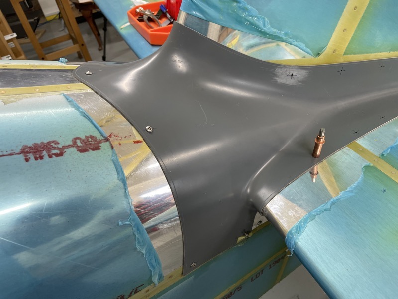
The Gap Covers fitted well, but needed fine tuning at the tailplane lower skin/cover interface.
I don’t think the tailplane will flex that much so close in to its anchor points, so I adjusted the fit for a minimum clearance, bearing in mind the aim is to reduce drag.
Once screwed in place, the covers are match drilled into the fin along their rear top edge.
I clamped them in place, but found it best to use a spare finger to prevent the cover from ballooning away from the fin during match drilling.

Vans suggest a 12″ #40 drill bit for this task, but I found a 6″ one was OK and easier to manipulate.
Empennage Fairing
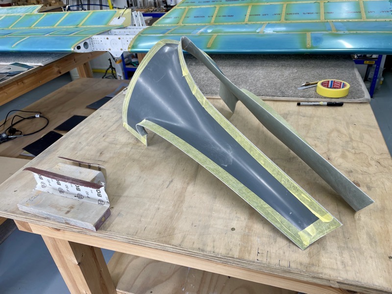
The F-01496 Empennage Fairing has to have an initial trim to 1/8″ outside of the scribe line.
I used tape to mark this, cutting first with a Dremel cutting disk followed by a sanding block.

The initial fit showed there was a gap where the Fairing met the tailplane leading edge.

As per the manual, this was sorted by trimming the top of the fairing at the fin leading edge a little bit at a time …

… until the fit improved.
The manual also mentions sanding down any thicker sections at the interface, but my fairing needed very little adjustment.
Now for the fun stage … how to “blind drill” the holes in the fairing to match the holes underneath.
I tried a bright light inside, which was hopeless due to the gel coat.
I tried using the magnets, which are supplied in the kit. But I found them inaccurate due to the range over which the outside magnet was able to move and remain stable … in other words I couldn’t guarantee an accurate mark.
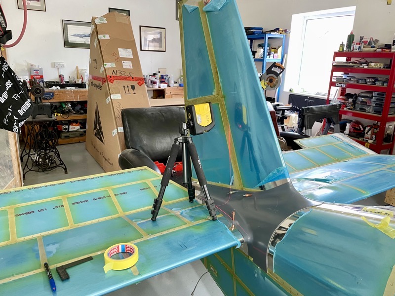
I ended up using my laser level, which produced good results.
You might also consider rubbing off the fairing gel coat at the hole locations to see if a light shines through enough to accurately pinpoint the hole positions?

Anyway, I quite enjoyed setting up the laser level to mark each hole …

… and then carefully adding the fairing without disturbing the level.
After marking and removing the fairing, it was easy to see that nothing had moved by checking the laser still accurately marked the hole.
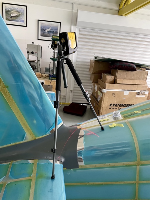
An adjustable tripod allowed stable placement for each hole.

Laying the level on the tailplane worked for marking the fin holes.
Marking the fuselage side holes needed the tripod placed on the floor. This meant the plane had to be kept absolutely stable, achieved by chocking all 3 wheels.
The manual suggests that you leave the top skin nutplates until after match drilling for the fairing, but I had already added them during early aft fuselage construction when access was much easier … I’m glad I did!
Since the nutplates were already installed, I used screws in place of clecos during the process.
The next job is to install the nutplates on the fin/tailplane holes.