


26-12 to 15 Riveting Seat Ribs to Bottom Skin
Seat Rib Angles
After riveting the Aft Gear Brace Assembly the outer Seat Rib Angles are attached initially with one rivet at the top, partially set so as to allow the rib to be adjusted.
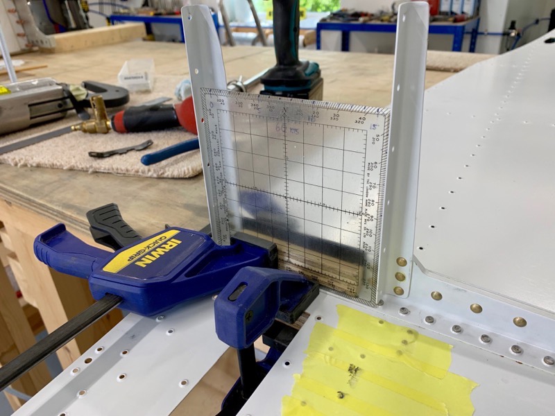
I clamped the Seat Rib Angles to a set square, then final drilled the 1/8″ holes to #30, and squeezed the rivets whilst clamped to ensure everything stayed square.
After back riveting the Aft Gear Brace Assembly to the bottom skin, a similar process is needed to attach the inner Seat Rib Angles.
My old navigation protractor just fitted between the ribs, so I used that to keep the inner ribs true.
Centre Bottom Skin

Having read other builders advice about riveting the skin to the ribs, we placed the structure vertically on the Bulkhead Assembly to allow easy access.
Here it is with JC5A jointing compound applied ready to offer up the skin.

As usual there are several rivets which are not set at this stage, and I found that viewing this page of the manual as a PDF on the computer helpful … zooming in made it easier to work out which holes had to be omitted.

Although the structure was quite stable on the bench mounted in this way, I still clamped it to avoid any traumas!

The skin was very wobbly at the top, so we attached two baggage ribs and clecoed the skin to them. This secured it nicely.
Power Outlet
A simple little job to rivet the power outlet, but as usual not that simple.
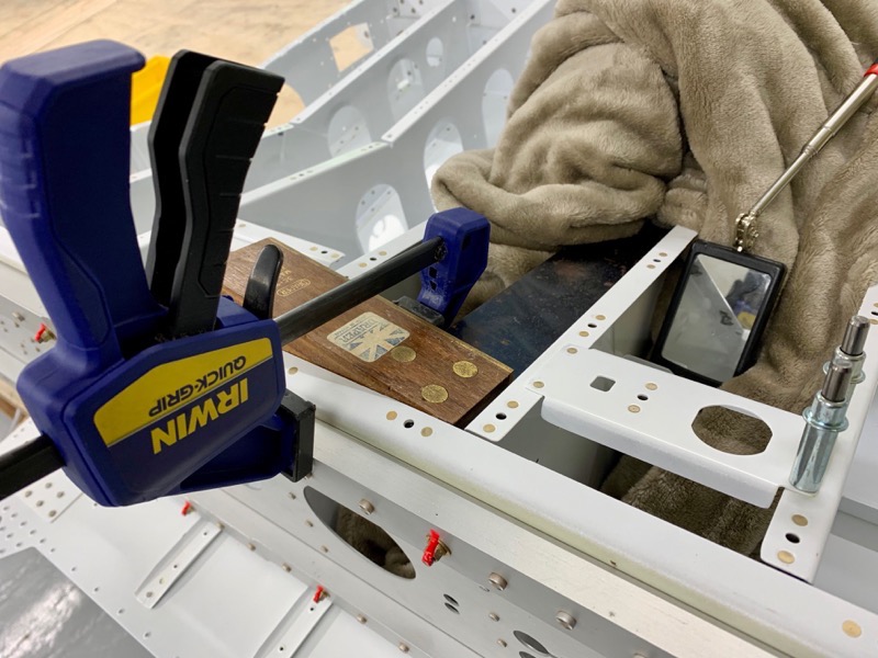
I found it best to clamp the ribs with a set square to ensure the power outlet rivets were set with everything true.
I used a little mirror to check the squeezer was positioned correctly on the shop heads.
Seat Rib Angles – LP4-3’s
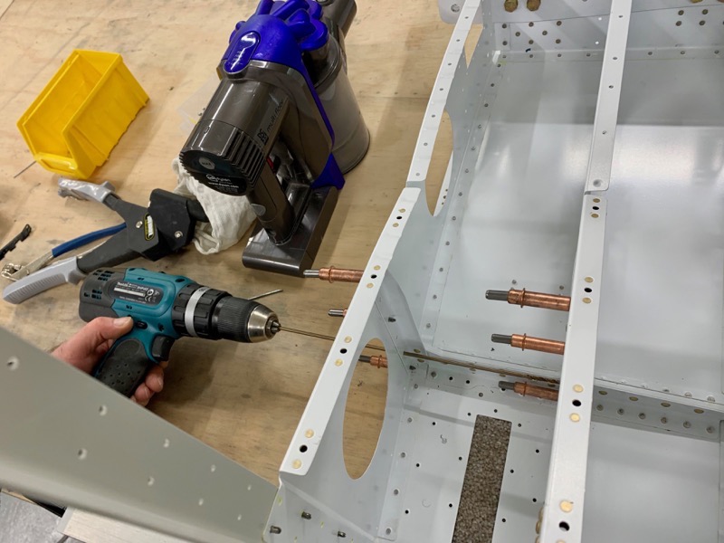
The inner Seat Rib Angles are pop-riveted to the F-01416-R Seat Ribs.
But I found that although the holes just about lined up, it wasn’t close enough to quite allow a LP4-3 to be inserted.
Eventually I gave in and final drilled the holes using a long #30 drill bit.

The next issue was positioning the pop riveter to get access to actually set the flipping things …
… after a bit of trial and error it’s possible to get them all set.


