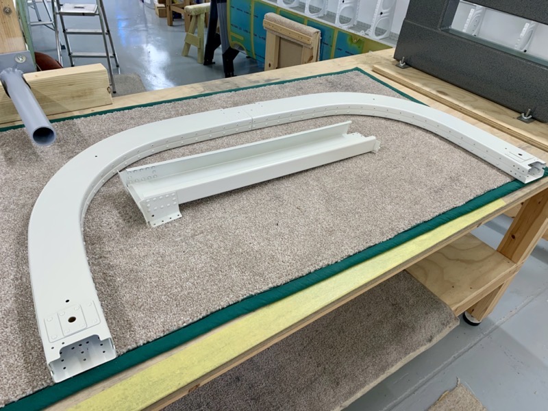
37-02 to 04 Building the Roll Bar Assembly
New section means deburring!
I removed the jagged edges with the Vixen File, and then finished off the edges on the Scotchbrite Wheel.
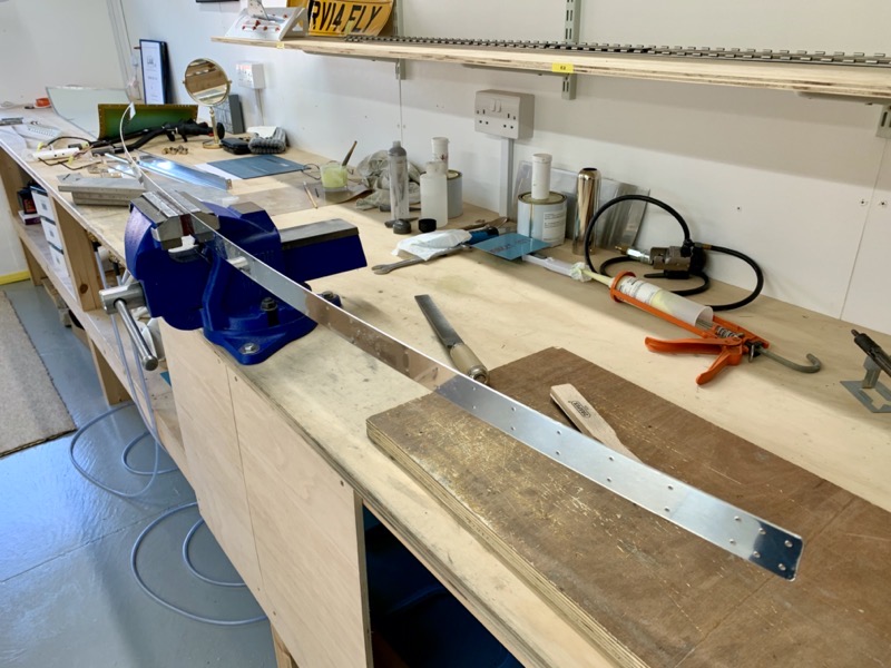
The Roll Bar Straps are long! They needed careful handling whilst deburring.
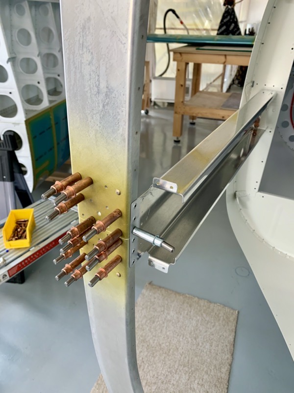
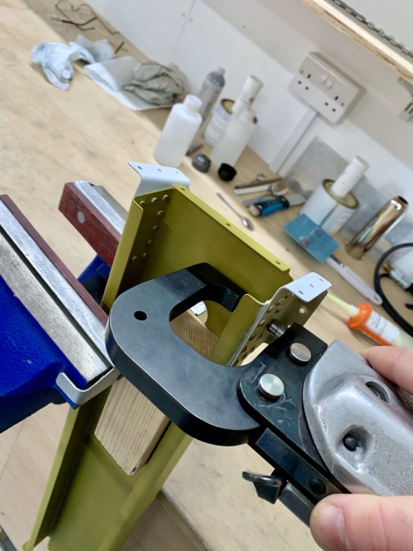
The Roll Bar Frames are clecoed to the fuselage to form a jig whilst 4 rivets are set on the Roll Bar Splice Plate.
To provide rigidity when setting the rivets I temporarily clecoed on the Roll Bar Brace (NB this is obviously not the final position for the brace! Attached as in the picture I could get the squeezer in position.)

Once all aligned, you can remove the Roll Bar Frame from the fuselage and set the other rivets.

This process is followed for both halves.
I had primed the areas where the Roll Bar Splice Plates fit.

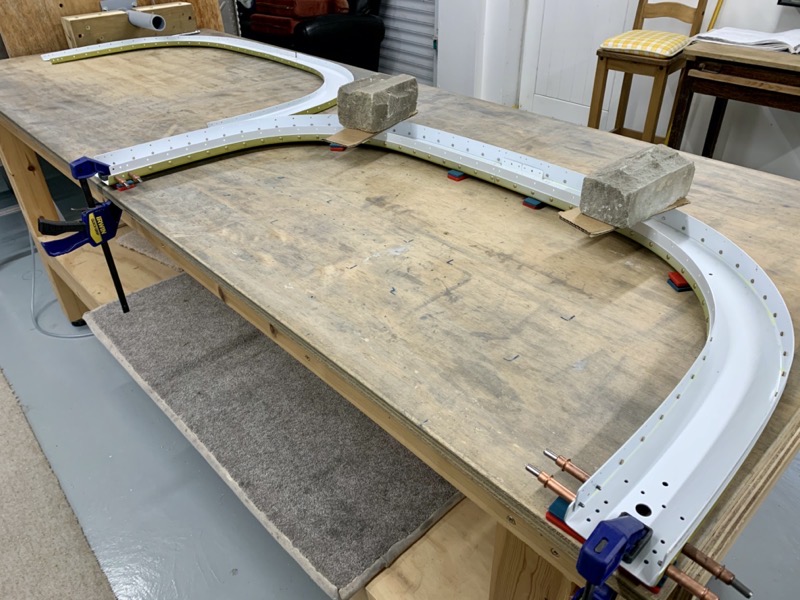
I gently drew the Roll Bar Straps over the edge of the bench to preform them to match the Roll Bar Frame curve.

Vans highlight that you need to be careful not to kink them adjacent to the holes … yes you do!

I made sure the whole structure was flat as I clecoed and final drilled.
A clear head required here, as there are the usual exemptions from machine countersinking etc.
It talks about making sure all swarf is removed from between the parts as you drill … but since it’s all clamped together I didn’t find this was a problem. But I did use the airline to puff in the gaps as a precaution.

This is from page 37-04. Might be easy to misread this detail view … only the FWD Roll Bars are machine countersunk on the middle tabs.
Once all the holes were drilled I primed.
The squeezer fitted just fine to rivet the Roll Bar Brace Brackets to the Roll Bar Brace.
Keeping everything flat when riveting on the Roll Bar Straps.
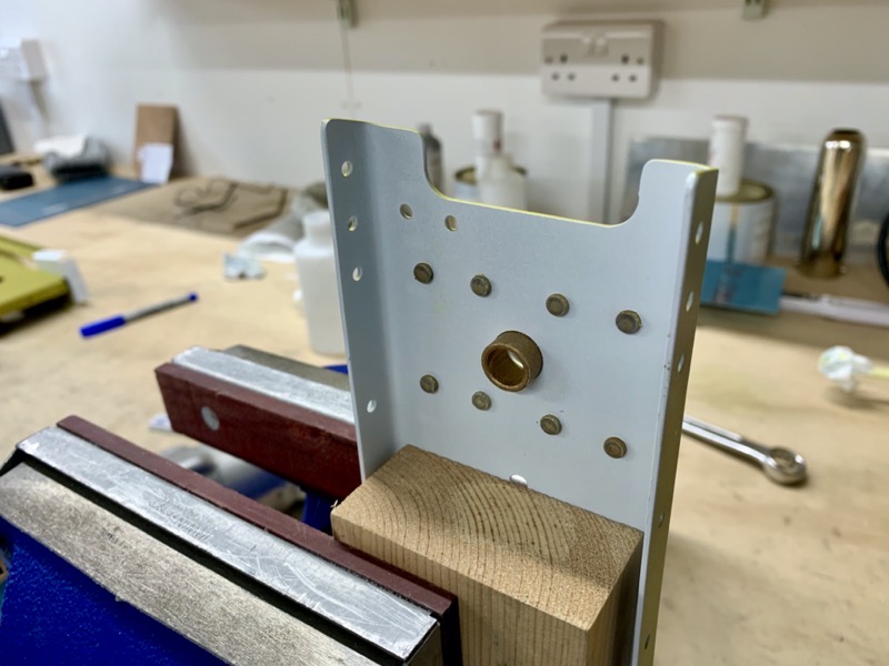
Here’s the little bush in the Aft Roll Bar Frame Assembly.

Lots of LP4-3’s and CS4-4’s to set … easy and enjoyable little job with my Pneumatic Pop Riveter.
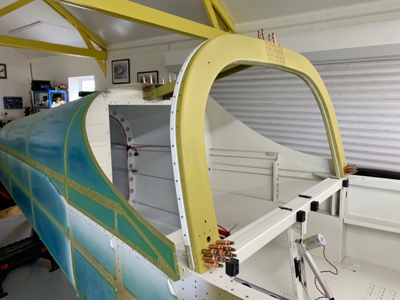
The assembly is clecoed in position on the fuselage ready for match drilling.
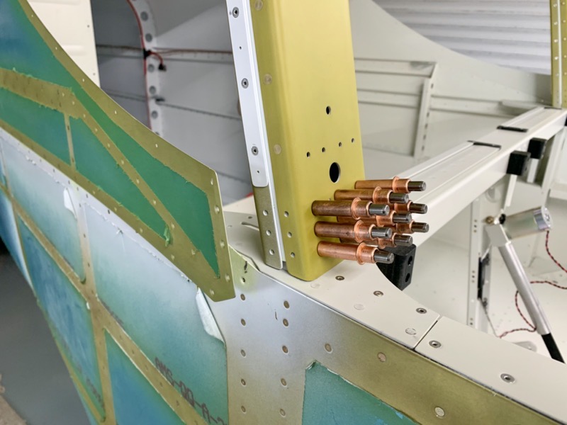
The Aft Fuse Top Side Skins can be gently eased aside to reach the side holes
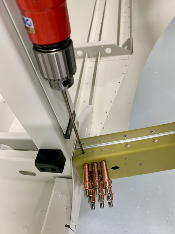
You need a long #30 drill bit to reach the lower side holes.
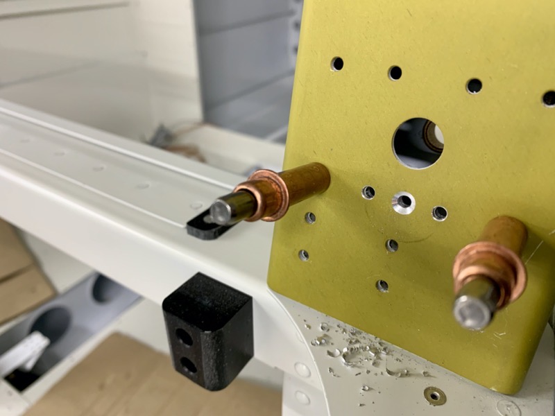
One hole each side is countersunk to fit a CS4-4 rivet.
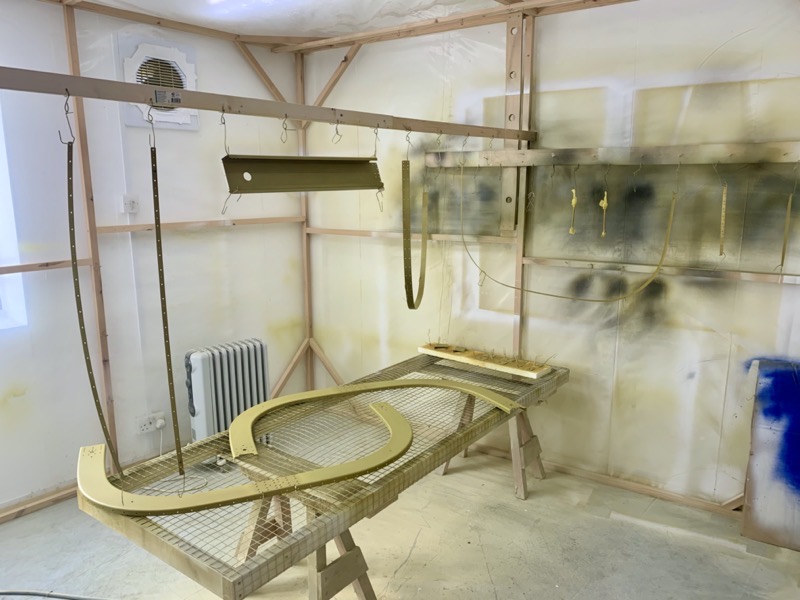
I then sprayed the assembly with my 2K Cockpit Paint prior to final installation.
I plan to install it a bit later to allow easier access while I fit GPS Aerials etc.