


13-03 Countersinking
There are a LOT of holes to countersink in the spars, I couldn’t face counting … but there are over 1000. You have to carefully study the manual to ensure they are machined to the correct size. But it really boils down to 4 types:
- Flush for a AN326AD3 rivet – for nutplate rivets & holes at some of the rib locations where the tanks fit.
- Flush for a AN326AD3 rivet + 0.007” deeper to accommodate the 0.032” skin
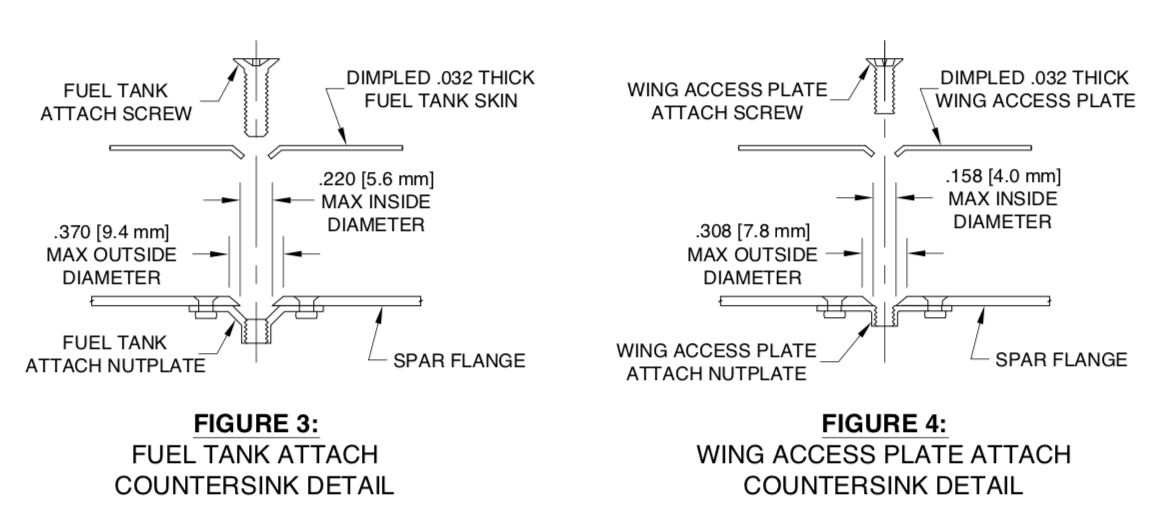
- Size to accommodate a #8 screw dimple, max outside diameter/min inside diameter specified in the manual. These are for wing tank attachment.
- Size to accommodate a #6 screw dimple, max outside diameter/min inside diameter specified in the manual. These are for access panel attachment.

Click here to view a nice informative video produced by Jonathan Hancock, a fellow RV14 builder in the UK, which explains the various countersink depths.
13 November 2023
Skin and Nutplate Countersinks
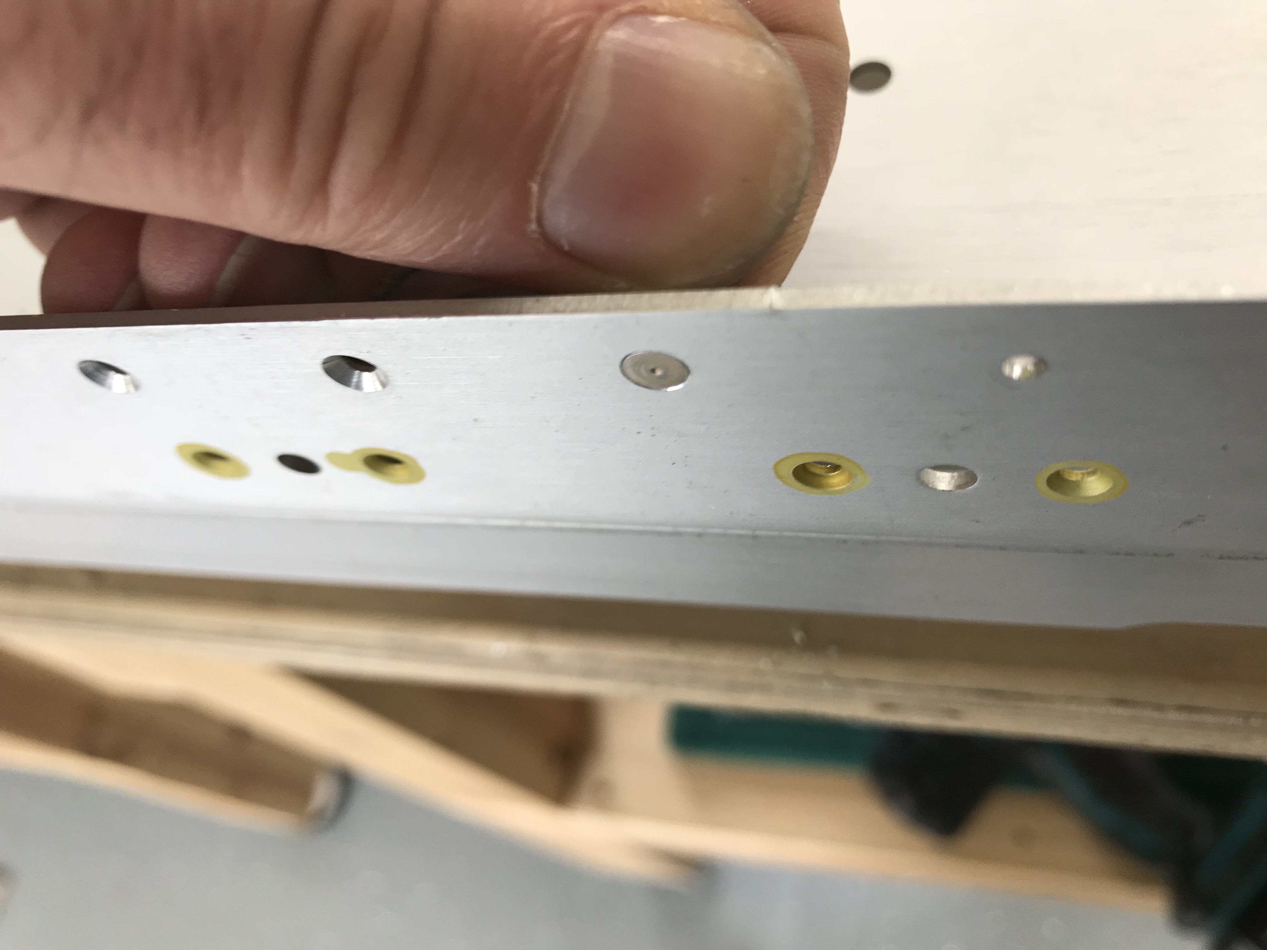
The skin and nut plate rivet locations are straightforward, just loads of them! This picture shows a countersink allowing for the wing skin, which is flush + 7 thou, as advised by Vans in Section 5 of the manual. I used the micrometer countersink tool to do these, checking each hole with a rivet head to make sure the depth wasn’t wandering. You rapidly attain an eye for the correct diameter countersink : )
I had spot primed the nutplate countersinks in anticipation of riveting the nutplates prior to countersinking, but I changed my mind as you’ll see below!
Screw Countersinks
Vans recommend these are done by first riveting on the relevant nutplate, then using a microstop countersink tool. The idea is that the nut plate thread acts as a locator for the countersink pilot. I’m sure this works, but I didn’t fancy it much. The problem is the countersink has to be quite deep before the pilot engages in the hole. There is a lot of metal to remove, and I could see it being full of jeopardy. Other people have suggested making a template and using this as a guide for the countersinking. That’s what I did too, using some scrap aluminium angle.
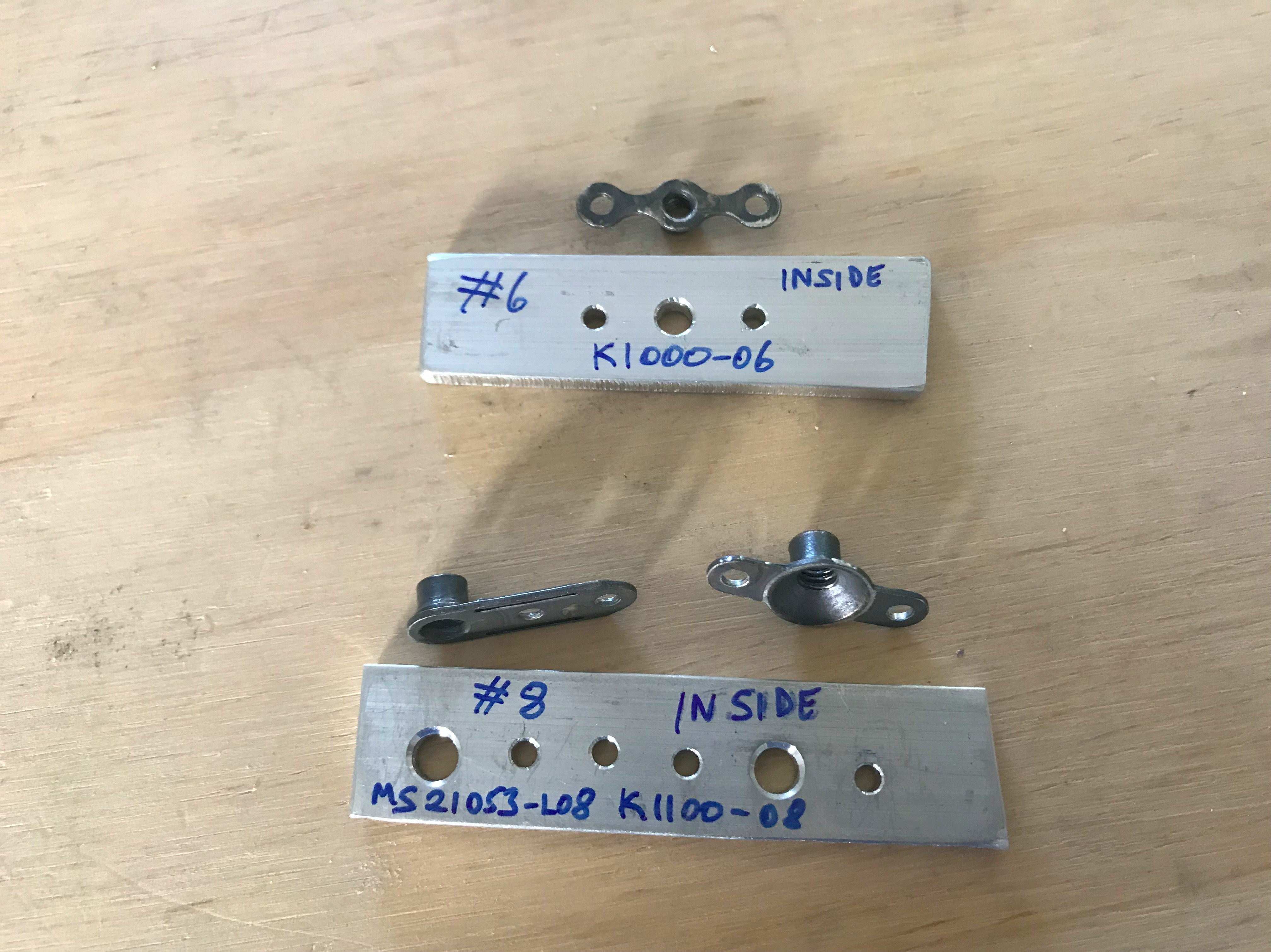
I made templates to replicate the #8 & #6 nut plate geometry, drilling the pilot hole locator with a #19 & #27 drill respectively to fit the countersink pilots. The spar holes also had to be final drilled with these to allow the countersink pilots to fit.
Aligning the Jigs
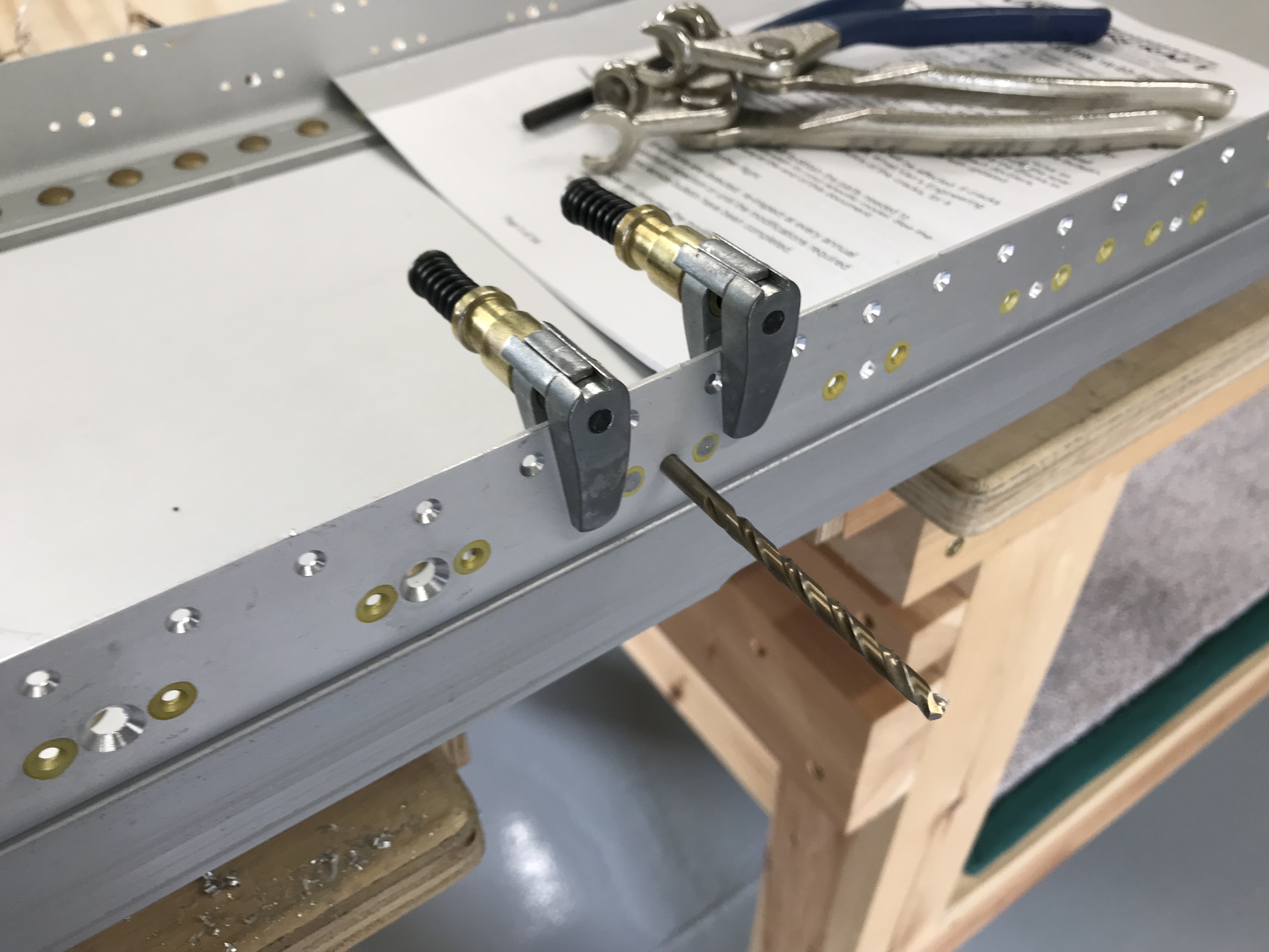
I aligned the jig in each location by centering with the relevant drill bit, and also inserting rivets. Once happy, clamps held it in place.

Finally I again used the microstop countersink tool to machine the spar.
I ended up deciding on diameters of 0.360 and 0.298 … this seemed to allow a good fit of the screw size dimples in a piece of scrap 0.032″ skin. The inside diameter is automatically governed by the outside diameter of course, and these values ensured the inside remained well within the tolerance. I set my digital calipers to the required diameter and checked the diameter of each countersink as I machined. I also used suitably sized drills to double check the inside diameters.
Machining

I used the microstop tool in an ordinary cordless drill, using a low speed to start the cut and speeding up at the end. Applying a higher pressure at the end also seemed to help stop chattering and produce a consistent depth. It all took quite a long time because of having to check the max diameters were not wandering!
Eventually all were done … phew!


