


19 – Wing Wiring Part 3 – Magnetometer, Pitot Heat & Roll Servo

This wiring was my first exposure to DSub Pins : )
Again, lots of advice on the web, the most useful I found being on the EAA site (Circular Plastic Connectors) and SteinAir.
I had bought a DMC AFM8 crimper a while ago, together with a K13-1 Postioner, which allows quality crimps on #20 standard contacts. These are used by Garmin connectors and also happily the Size 2 CPC’s.
SteinAir sell a much cheaper crimper, but do suggest the DMC version if you are planning a full avionic install … “money well spent” I think was the phrase. We’ll see???

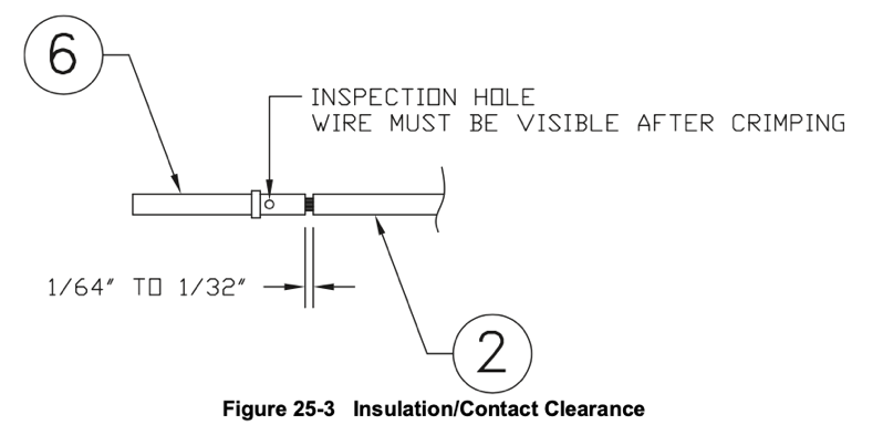
The Garmin G3X Install Manual advises how the wire should be stripped for the crimp.
And crimping with the AFM8 couldn’t be easier … the Positioner decal tells you what number to set on the tool for a given wire AWG.
Once set the pin is pushed gently into the positioner with the wire, and the ratchet release ensures an accurate crimp.
Magnetometer

The Garmin GMU 11 Magnetometer install kit includes the DSub Connector.
Since I’m planning to connect the CanBus after the wings are attached, there were only 3 wires to connect at this stage.
The G3X Install manual has pin out documentation showing pinouts. The connectors also have numbers on them, if your eyes are good enough!
The pins clicked into place very easily, having triple checked I was putting them into the correct holes!

I loosely held the GMU 11 connector together with tape, leaving the heat shrink tube ready to inert the CanBus daisy-chain later on.
This should be character building, underneath an attached wing : )
Pitot Heat
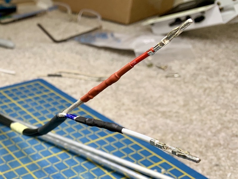
The Garmin GAP26 Pitot Probe is supplied with 4 wires, which depending on your supply voltage have to be wired in a particular way. For a 14V system the wires with the black band are wired in parallel.
To achieve this I used solder sleeves to connect each of the 2 pitot wires to a 14AWG wire …

… with a Molex pins crimped on the end ready for a Molex plug.

In the wing I used the hole for the mechanical Stall Warner wire to attach a P-Clamp.
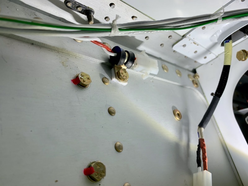
It needed a little spacer to clear the spar doubler.
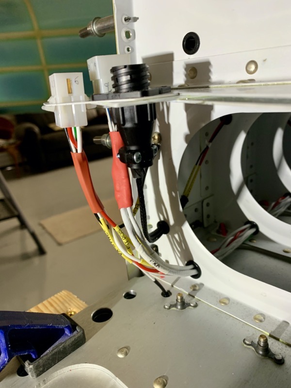
This picture shows the wing pitot wire supported by the P-Clamp ready to connect the Molex attached to the Pitot Heater wiring, visible on the right side coming out of the pitot mast.
Roll Servo Backshell
As previously mentioned, I decided to remove all unnecessary connectors from the Roll Servo wiring harness, and also wire the CanBus as documented in the latest Garmin Installation Manual.
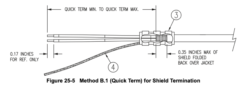
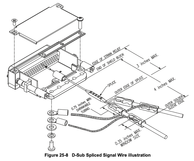
I used Solder Sleeves for both the Shield Termination and to join the HI/LO CanBus Splices.

The manual shows max/min dimensions for the various connections, and make it quite challenging.
I used the recommended Self Sealing Silicon tape to provide protection for the wires in the strain relief.
Annoyingly the Garmin connector kits do NOT contain the hardware to attach the Shield Drains to the back shells. The manual does, however, clearly explain that you’ll need:
- Ring terminal, #8, insulated, 18-22 AWG
- Screw, PHP, 8-32x.312″, Stainless
- Split Washer, #8, (.045″ compressed thickness) Stainless
- Flat Washer, Stainless, #8, .032″ thick, .174″ID, .375″ OD
or the equivalent. More AMU’s!

My first completed Garmin connector. Fingers crossed it will work!

Rather than use the Vans Roll Servo connector bracket, I decided to route the wiring above the servo via a P-Clamp. This will keep it away from the control rods.
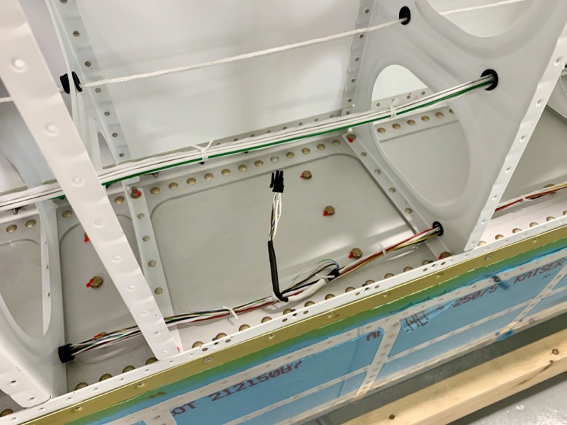
I used a slightly larger bush to exit the wires from the servo bay, before routing them forward to the Vans suggested bushes near the spar. This routes them inboard underneath the aileron trim servo, making it easier to connect up the trim power wires which come from the Roll Servo …
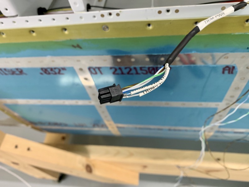
Aileron Trim Servo
… here they are, wired into a Micro Molex 3.0 connector together with the 3 data wires which run inboard to the wing root.
I left enough service length to make connecting the servo attached to the inspection plate a bit easier.
Many people do not like these connectors, and I did consider various alternatives, but in the end, using my experience gained ages ago when wiring up the Elevator Trim Servo, I decided to use them as supplied by Vans.
Using that technique I was happy I could achieve good crimps, and be able to have good cable strain relief with heat shrink tubing.

Once inserted these Micro Molex Pins are inserted … there is no easy way out!
The Ray Allen power wires are BOTH white, so there is no way to be sure that the polarity is suitable for your installation.
The Ray Allen instructions merely say if the servo runs in the wrong sense, swap them round. Great.
Not feeling especially lucky, I’ve left my 2 power Molex pins loosely placed in the connector until final configuration … hopefully this will avoid another hurdle later on?

For some reason Vans suggest you position the Molex connector on the outside of the servo support for their harness. But as you can see in the picture, I decided to drill another hole to come back inside with the wires, and hence have the plug connector facing outside the support, making it easier to connect the wing socket.
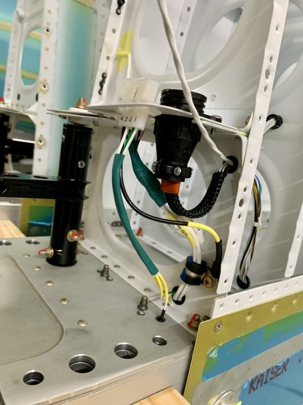
Wing Root Connectors

After lacing the harness to make sure all the wires were sitting comfortably in their resting position …

… I again took a deep breath and cut them all to length, and crimped on the DSub Pins for the CPC.
It took a while to make sure I was inserting the pins into the correct holes as depicted on my wiring diagram.
I used some self sealing tape and cable netting tube to provide strain relief.
This is the left wing root connector completed.
Before closing up the wings I did continuity checks to ensure all the wires were in the correct pins, and that no wire screens were short circuited.
I’ve left enough CanBus wire from the Roll Servo to connect up to a “yet to be decided Garmin box” behind the instrument panel after wing attachment … I hope!
The wings are now ready for the lower wing skins to be attached.


