41- More Wing Attachment – Flaps, Ailerons, CanBus
I had decided during the initial wiring phase that I would attempt to avoid the use of connectors at the wing roots for the CanBus, OAT Probe and Archer Antenna RG400.
This was to follow advice from Garmin re the CanBus, and to minimise signal loss for the OAT wire and RG400.
It was a little more work and needed planning to ensure all the wires could be threaded to their destinations, but actually it wasn’t too difficult.
I had left a length of cord in the right wing to pull the RG400 through from the fuselage. This worked well until I accidentally caught the string with my sleeve and pulled it out of the last couple of ribs … Foohey Fudge Cake!
Never mind, it wasn’t much of a hurdle to feed it through the ribs by reaching through the wing access panels.
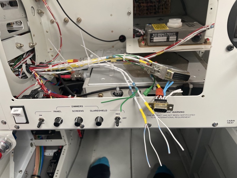
CanBus

Here is the CanBus from the Aileron Servo, RG400 and the OAT wire. The OAT wire is hidden in the picture, but follows the path of the CanBus.

This is the left wing root, showing the CanBus wiring from the Pitch Servo to the GMU11 Magnetometer, and then back out of the wing to meander it’s way to the next LRU in the cockpit.
I used tie wraps to provide additional support for the wing root wires, using self-sealing tape to prevent any wire chaffing.
Also seen here are the AOA and Pitot tubing.

It was a bit awkward to wire up the Magnetometer connector under the wing, and to daisy-chain the CanBus … I left a service loop in case a goof caused a second attempt!
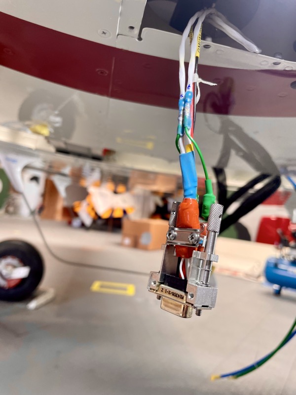
But all was well … here is the finished connector …
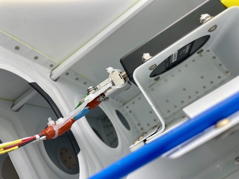
… and this picture shows it plugged into the GMU11.
I threaded the Aileron Servo CanBus up through the fuselage through the pre-positioned HeyCo Bushes, finally arriving behind the MFD.
The OAT wire followed a similar path, but veered off left behind the centre panel to its destination … an ADHARS connector.
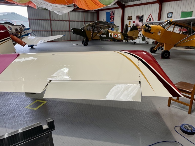
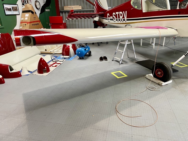
Flaps & Aileron Attachment
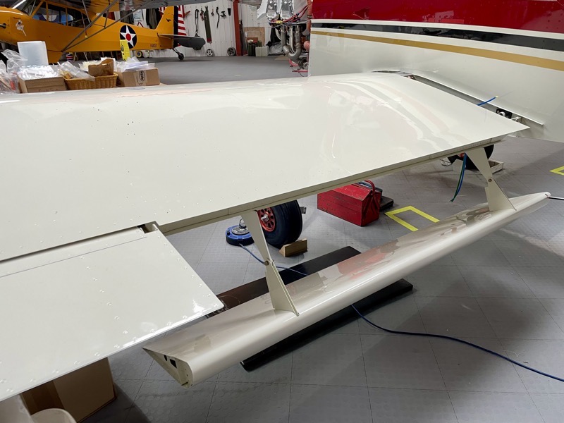
I used new hardware to attach the Flaps and Ailerons.

The Flap Pushrods fitted with virtually no adjustment needed … the specified lengths were spot on.
At this stage I hadn’t re-installed the avionics, so I used a small 12V battery to motor the flaps through their range to check the pushrods.

The keen eyed will spot an incorrect bolt here, used to temporarily attach the aileron pushrod.
We did not want to continually wind our correct bolts in and out as we fine tuned the pushrod length.
The flaps are set fully up against their stops in the reflex position, and the aileron bellcranks set neutral using the template. Then the aileron pushrods are adjusted so that the ailerons align with the flaps.
An enjoyable little process. All the careful work several years ago ensuring straight trailing edges paid dividends … casting an eye down each wing tip along the wing trailing edge revealed a pleasing sight! : )