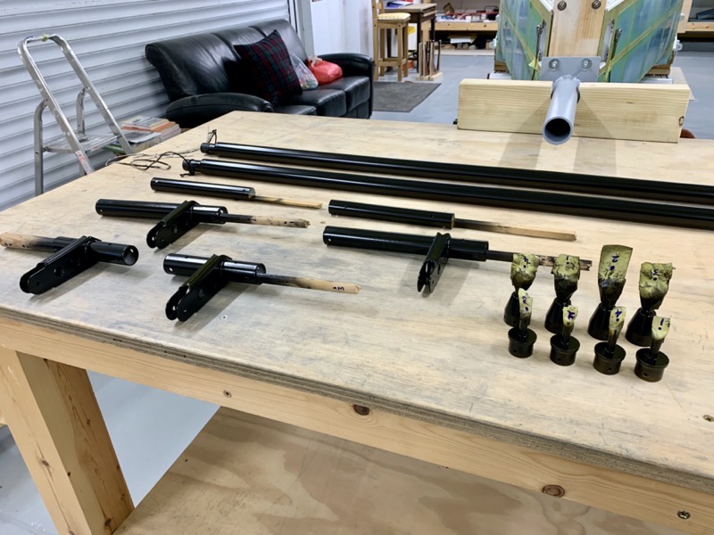
23-06 & 07 Aileron Torque Tubes
Only one of the VA-162 Pushrod Ends had a slightly too big diameter to fit inside its aileron torque tube, so that one needed a bit of fettling.
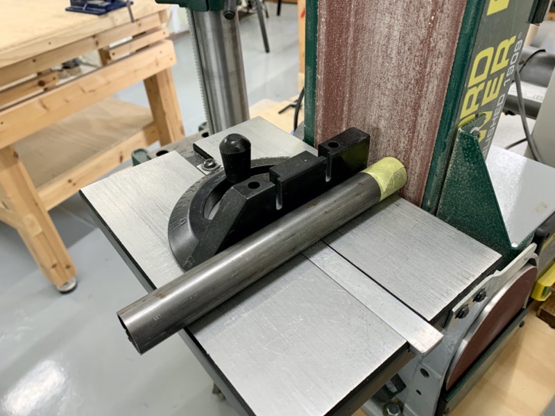
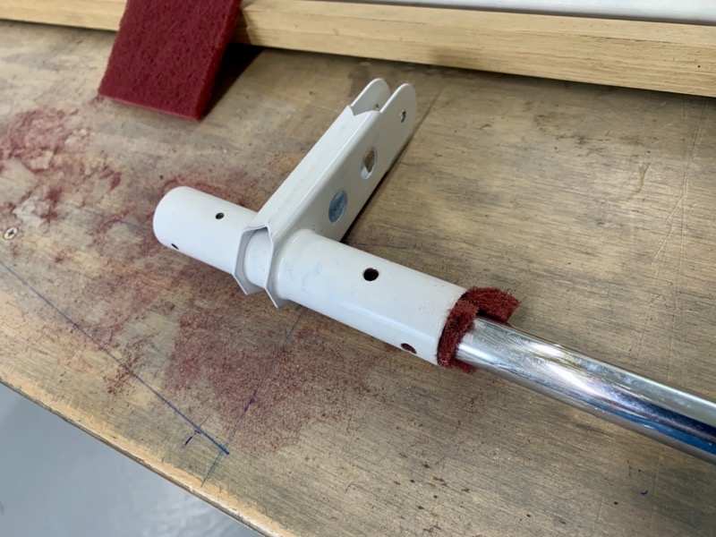
I used my vice clamp to secure the CS-00009’s for match drilling.
But the WD-1014 Aileron Torque Tubes wouldn’t fit in the clamp. So I made some V-Blocks to get the job done.
The CS-00009B Torque Tube Collars have to be cut to length, so I fine tuned them with the vertical sander.
The manual has a typo here, which caused some head scratching to find the material from which to make them. The manual says make from WD-1014PC, which meant I was looking for a powder coated part, and of course is one of the Torque Tube welded assemblies anyway?? When I searched for CS-00009B on the Vans online parts list, it turned out to be steel tubing ST4130-035X7/8X22.
Match Drilling Collars
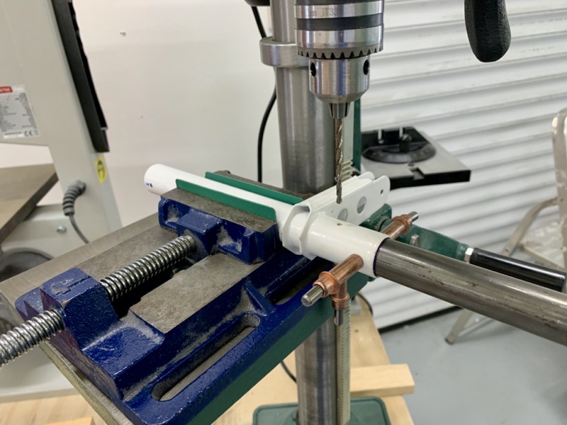
These holes are match drilled, and eventually need to accommodate AN3 bolts. So the holes have to be accurately drilled all the way through the tubes.
I came up with the following method:
1. Match drill each hole #30, clecoing as each is drilled as per the manual advice.
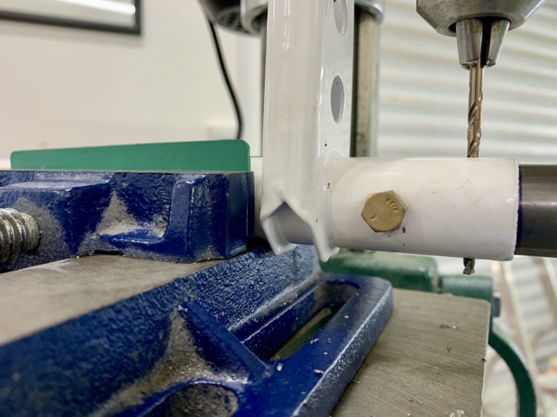
2. Once opposite holes have been drilled, align the torque tube by lowering the stationary #30 drill bit through both holes.

3. Having re-clamped the torque tube, I then opened up both holes to #17 by drilling all the way through.

4. And then finally reamed them to 3/16″.
This method produced accurate holes with the AN3 bolts fitting snuggly with zero play.
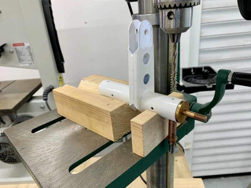
Jigging the Torque Tube Assemblies
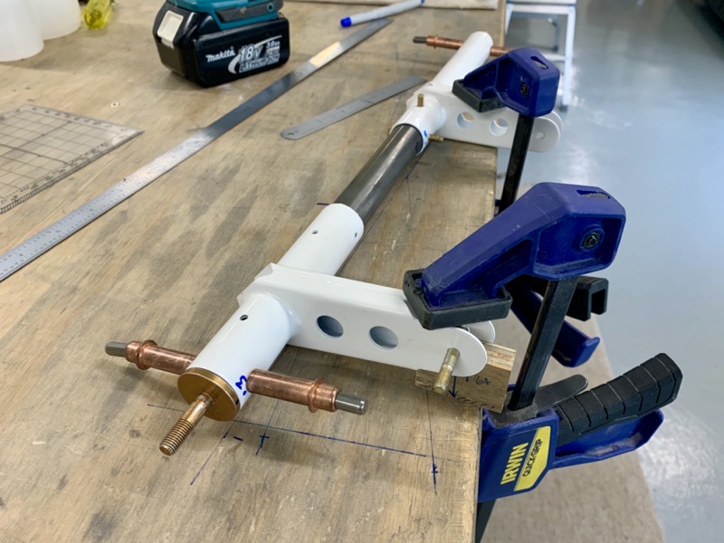
Jigging the Fwd & Aft Torque Tubes on the Collar needed some thought.
The angle is straightforward, using a spacer block.
But there is a 1/32″ tolerance on the overall length … hmm.
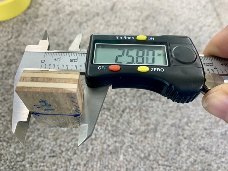
The manual has another typo at this point, in the text specifying a 1 1/64 [25.8 mm] thick spacer block, but the diagram saying 1 1/32 [25.8 mm]! Well, I reckoned since 25.8 mm is 1 1/64″, then that was what was required.
I machined a block on the vertical sander, then marked the position that gave an accurate 25.8mm.
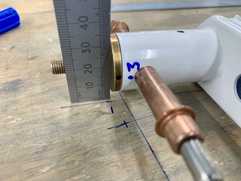
To achieve an accurate length, I marked the bench with knife lines 17 49/64″ apart (mid tolerance), and then used a steel rule to check the end plane of each Pushrod End was vertically above the mark.

I match drilled two #30 holes with the workpiece clamped to the bench.
Then I removed it from the jig and used the same previously mentioned method to finish the holes.
Priming & Painting
I attempted to scuff the inside of the tubes ready for priming.
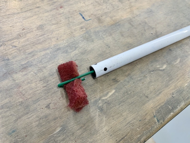
I used wire to drag scotchbrite through the small tubes.

And used some scrap wood to push it through the larger tubes.
Same for all the degreasing.
Then I poured primer down each tube, rotating etc to try and get complete coverage inside.
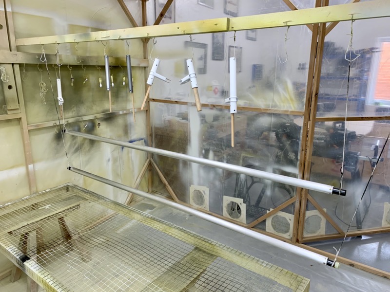
The non powder coated pieces need priming/painting on the outside. Since the powder coated parts looked a bit unsightly after pouring primer down inside them, I decided to spray a light coat of paint on them as well.
I carefully marked each piece so that I’ll be able to assemble everything back as it was match drilled.
We’ll see how I get on with that later : )