


Trailing Edges – Elevators 09-23 & 24
Having enjoyed success using a straight piece of Aluminium angle for the rudder TE, I decided to adopt the same technique for the Elevator and Trim Tab TE’s.

Used Aluminium Angle match drilled to the TE hole spacing to keep everything as straight as possible. I had attached this during the proseal bonding stage, whilst bonding the double sided tape on the TE. As it happens, the hole pitch is exactly the same as the Rudder TE, so was able to use the same piece of angle with a few extra holes drilled.
Squeezer, not the gun!
Rather than cope with the dynamic rivet gun technique recommended by Vans, I again decided to partially set each rivet, then use Cleaveland’s RV-14 SAFETY PIN SQUEEZING TOOL set to finish off. Started in the centre, then worked out every 5th rivet using the enlarged holes in the angle.

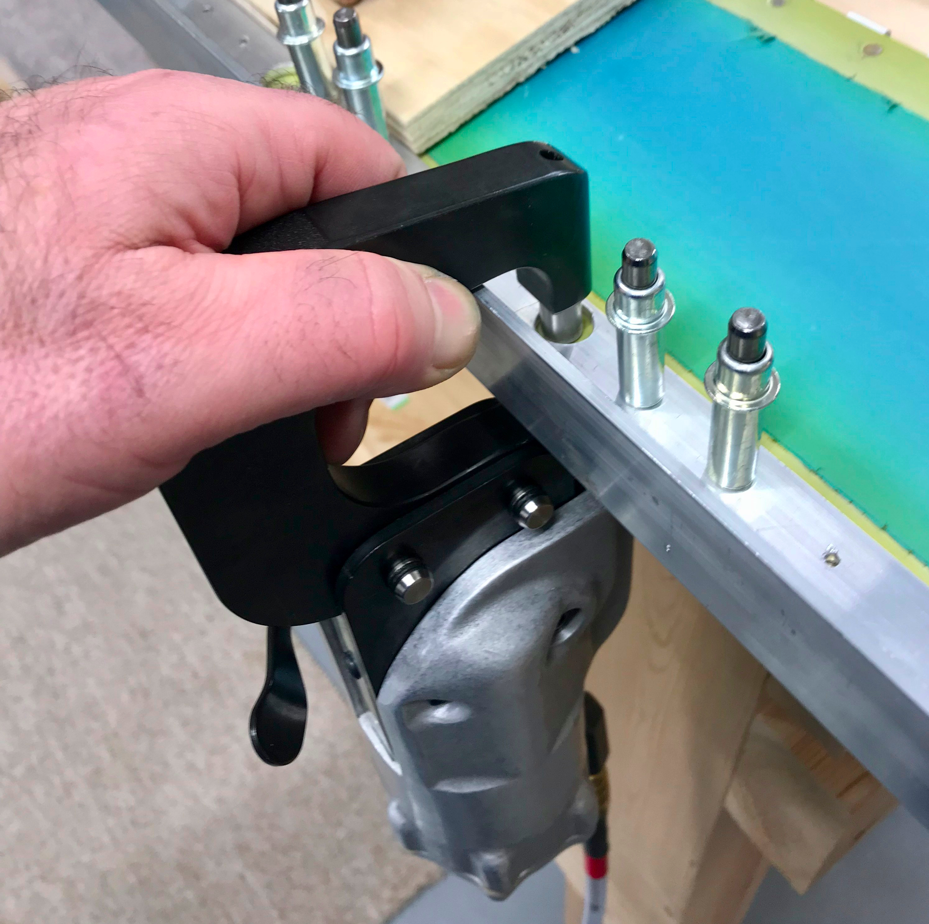
This was the set up on the Squeezer to partially set the rivets. Care was required on the manufactured head side to ensure the die did not put a smiley on the skin. I found it best to position the yoke deep enough so that the head was on the edge of the die.
RV-14 SAFETY PIN SQUEEZING TOOL
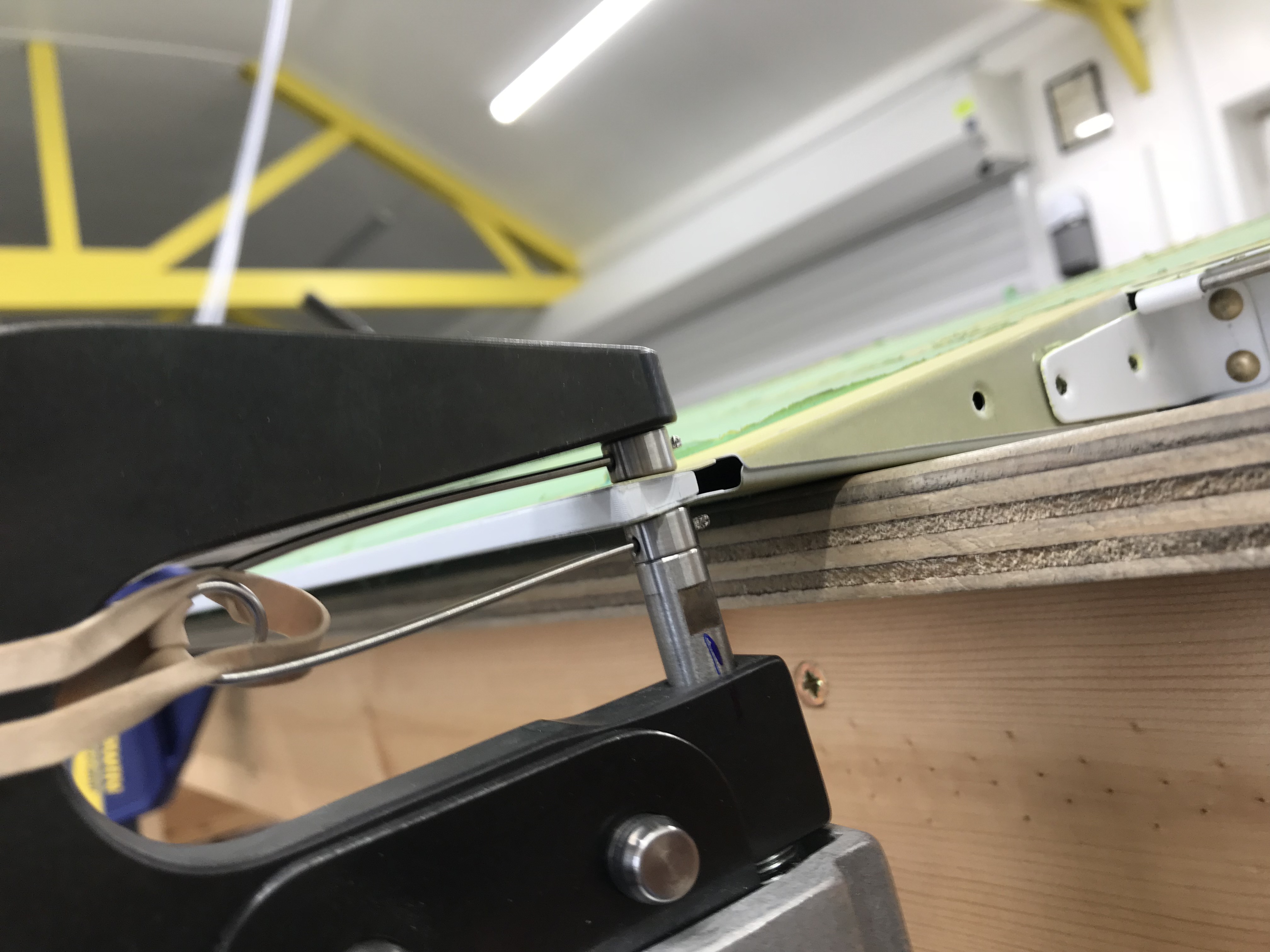
Here it is in action. Takes time to adjust the set to ensure the shop head is completely flush with the TE profile. Of course this will vary due to the taper unless you position the yoke in the same position each time. I found this easy to judge visually after a few rivets.
Trim Tab
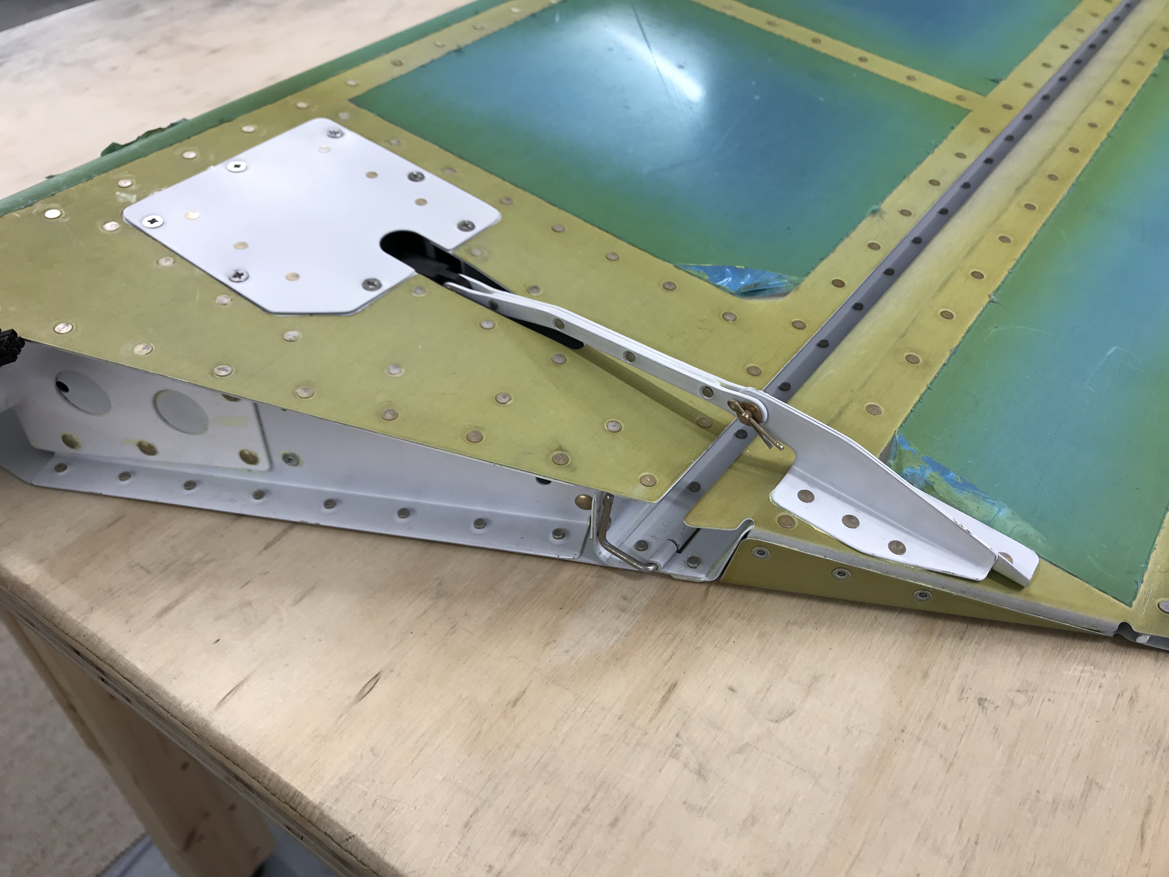
Having finished the TEs, I attached the trim tab together with the servo assembly.
Relieved to find the tab hinged freely and no play in the control linkage. I didn’t do the hinge safety wire, or completely adjust the clevis pin since I’m sure the tab will have to come off again for painting etc.
Test fit of Elevators

Having noticed that the L Elevator Horn had not been welded at a perfect right angle, I was concerned that the horns would not be within tolerance to accept the maximum number of washer shims either side of the pushrod. So I decided to do a test fit and see!
First job was to attach the rod ends, and I found them very stiff to attach since they are screwing into the nutplates. I managed to find a piece of plastic to protect the rod ends as I used some mole grips to wind them in to the manual suggested initial position.

I subsequently purchased a ROD END BEARING ADJUSTING TOOL when it was time to finally adjust after painting etc. I recommend one of these to make this process easier, since it fits into the available space more comfortably.

28 June 2023
After spending some time adjusting the rod ends in/out slightly, I managed to get it all about right I think. Happily the gap at the horn pushrod end is OK, so panic over.
I aligned the mass balance horns with the stab, took a deep breath, and peeped down the TE to see what the alignment was like. Not too bad … I reckon there is a slight twist in the right elevator, about 4mm at the root. Having consulted the forums etc, it would appear to be a common problem. The best advice when the time comes to drill the horns, is probably to align the mass balance tabs and accept the slight error on the inboard TE. The aerodynamic effect will be imperceptible, and the slight TE misalignment will not be visible since the rudder blocks the view : ) Anyway, I’ll decide later and now get the lead weights sorted.


