


44 – Spinner and Propeller
Propellor Governor
We fitted the Propeller Governor before hanging the prop, and it had a fancy gasket with a gauze section, whose convex shape needed to fit inside the governor body.

The governor only fits in one orientation, but the control arm and stops can be positioned independently to correctly match the cable bracket, which attaches to the governor.
The MT governor choice depends on the propeller type. We have a MTV-12-B-C/C183-59b prop … and the important bit about all those numbers is that it has blade counterweights. We chose this option because it has three advantages:
1. If the engine oil pressure drops, this means the blades coarsen, thus reducing RPM, rather than risking the propeller overspeeding due to them moving to a finer pitch.
2. If the engine fails, the blades automatically move to coarse pitch, reducing drag for the glide.
3. Due to the EarthX battery, lighter EXP119 engine and composite prop, it’s possible the CofG might be further aft than desirable. The counterweights add approx 10lbs which might just help.
Anyway, all this means we needed a MT P-880-3 Governor, which accomodates the above configuration.
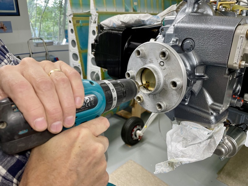
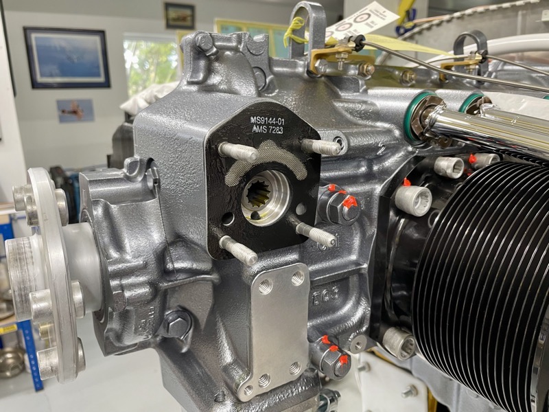
Lycoming ship the engine with a blanking plate over the prop shaft.
This needs to be removed, since this is how the oil from the governor gets to the propeller.
We drilled a few holes in the surprisingly thick plate, and then used a screwdriver to lever it out.

Be ready to catch some preserving oil!
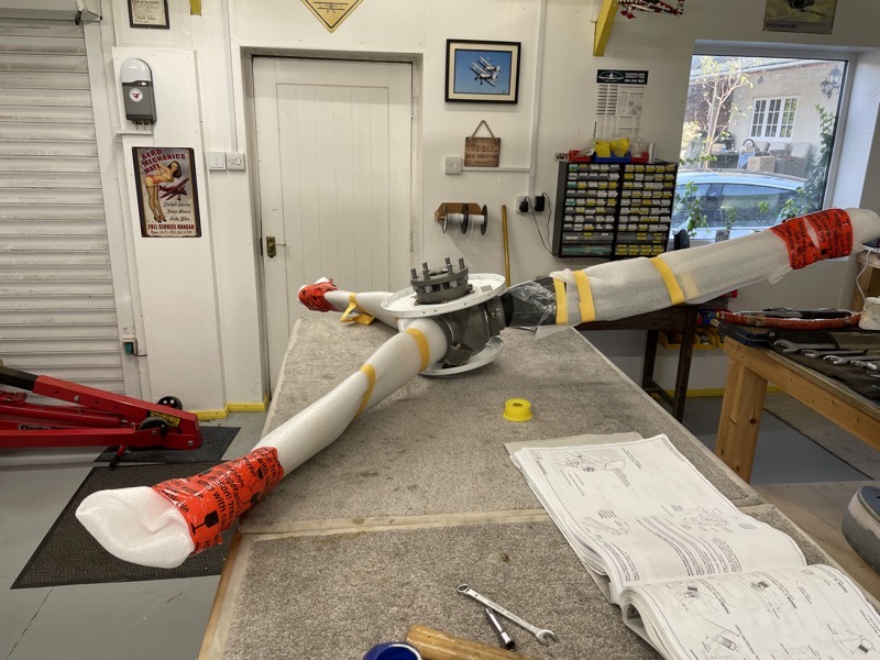
The prop had arrived in a giant Toblerone-shaped box, so after removal we placed it on a workbench to inspect our purchase and get familiar with the hub.

The attachment bolts are already installed in the structure, and have limited fore and aft movement.
This means that as the prop is offered up to the engine, whilst keeping it perfectly aligned, the bolts have to be iteratively screwed in as the unit is progressively pushed into place.

There is an O-ring which is very important to confirm is seated correctly … this prevents oil leakage from the hub.
Also one bolt shoulder hole is smaller than the rest.
And on inspection of the engine prop flange …
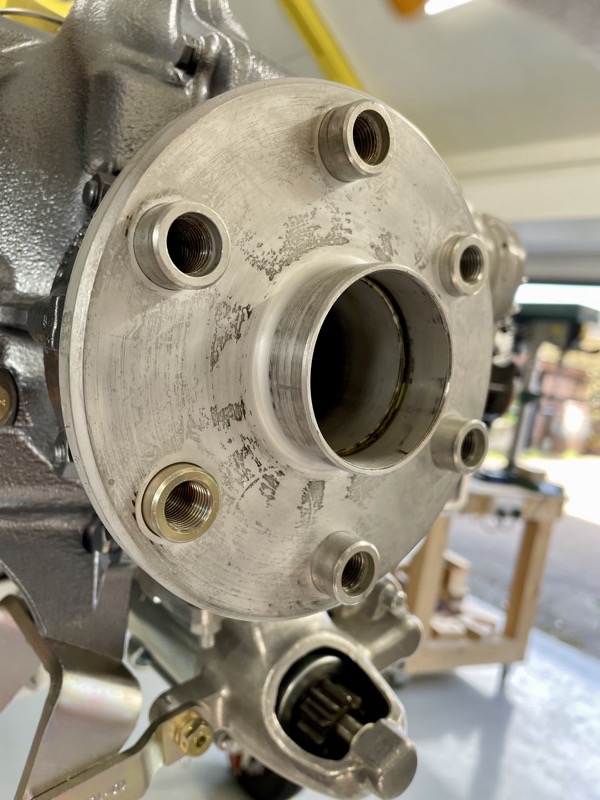
… as seen here, there are two stud locators which will be flush when the starter ring is in position, ie they are shorter than the rest.
Hence you have two possible orientations for the prop, because the smaller prop shoulder hole has to be over one of these two flush positions.

The engine prop flange and the O-Ring in the prop are lightly oiled to ease assembly.
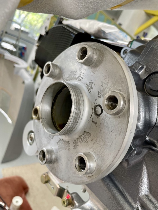
Lycoming have marked an “O” on the prop flange, and this needs to be aligned with …
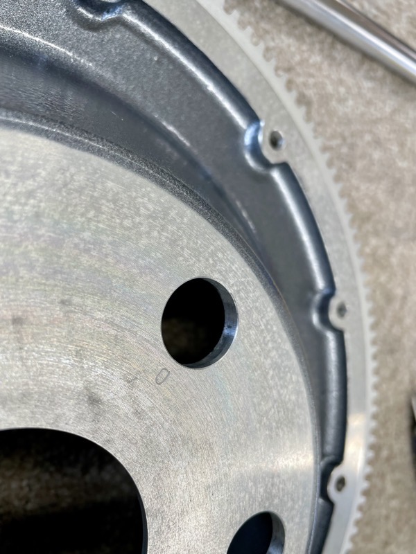
… an “O” on the starter ring gear.
This ensures the timing markings on the starter ring relate correctly to the position of the piston in cylinder 1.
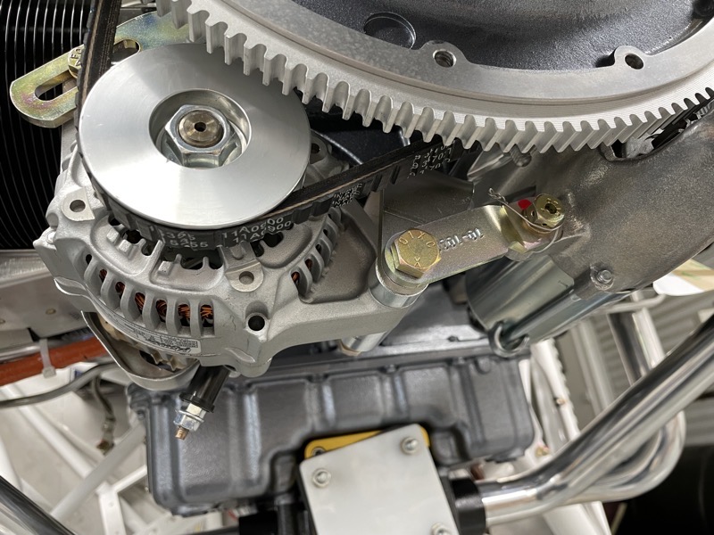
We are using a Plane Power alternator supplied by Vans for the primary, and we fitted this prior to installing the prop.
It took a while to find the correct document on the Plane Power web site … lots of numbers etc which didn’t really match the unit in our hands.
I could easily have a rant about documentation for all these third party items, but I’ll spare you!

Lots of bolt torque values to find as well, again sprinkled liberally in the Lycoming manuals. You are directed to a generic Lycoming Manual, the latest version of SSP-1776-5, which apparently has a value for one of the alternator attachment bolts. Goodness knows why this unintelligible document is specified for just one of these bolts, especially as we couldn’t find it in there anyway!
Whoops, a rant slipped out : )

We made sure that the alternator belt was as perfectly aligned as possible with the pulleys.
Propeller Attachment
This was the fun part!
We had originally planned to fit the propeller temporarily for the cowl alignment, but having seen the time consuming process of mounting on the hub, we decided to fit it permanently.
Hence we fitted the alternator first for easier access without the starter ring in the way, and most importantly, made sure we didn’t forget to fit the alternator belt!
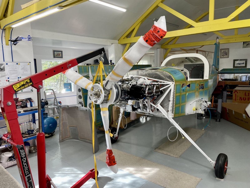
The prop had to be carefully positioned during attachment, and so due to its weight, we found it much easier to use the hoist.
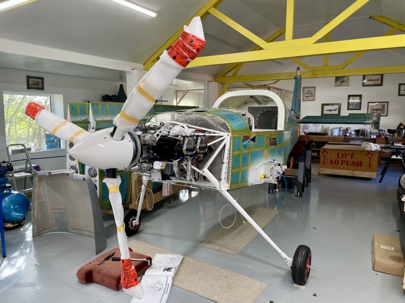
As the bolts are iterively screwed in, the prop must be gently slid into position, having made sure that the small hole coincided with a flush stud shoulder.
We secured it enough to locate snuggly, but will torque up later.
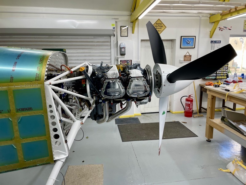
It was a real pleasure to simply fit an MT spinner, avoiding a lot of work making one in Section 44 of the manual … : )
I’ve been excited throughout the build, but now am getting really excited!


