


Fuselage Wing Root Connectors & VHF Antennae
Most of the last couple of weeks has been spent at the computer planning the “Backbone” of the electrical installation. More of that later … !!
Wing Root Connectors
But I did move a few things on in the workshop.
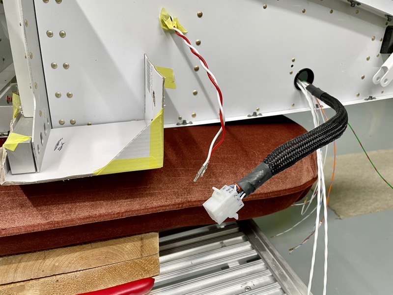
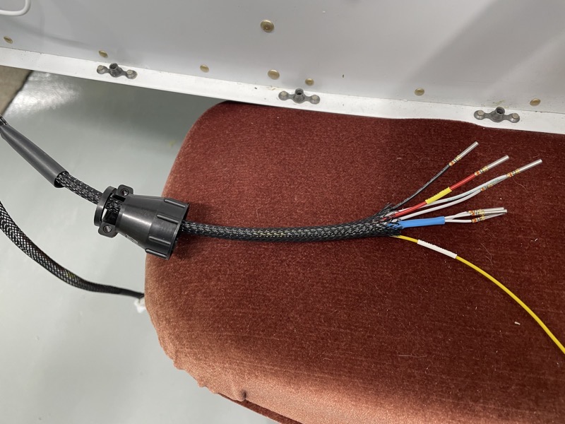
I had lots of wires protruding from various holes in the fuselage wing root which needed to be coerced into connectors and tidied up.
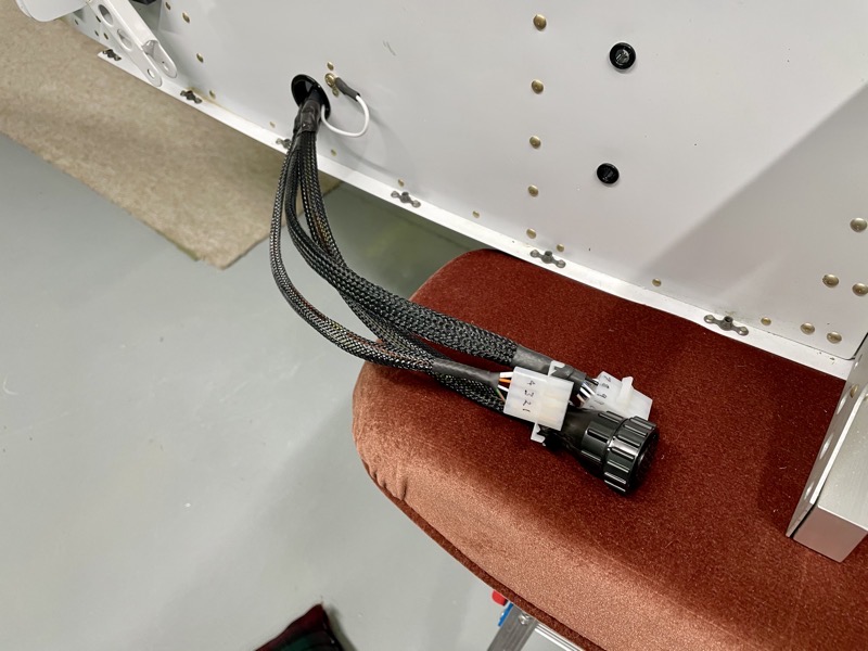
Here is the left side, showing the twisted pitot heat wires routing … the aim being to keep them away from the Magnetometer data wiring.
I clearly marked pin numbers on the connectors, triple checking I was about to insert the pins into the correct holes. I find it just about impossible to reliably remove the Molex pins once inserted, even using the appropriate tool.
For obvious reasons, I couldn’t afford to cut the wires too short!
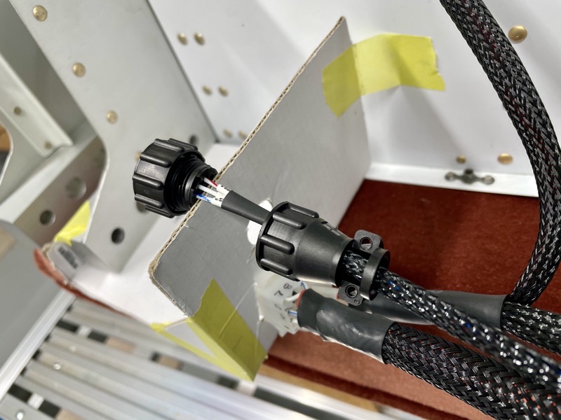
So I used my cardboard template to double check the connectors will easily reach their other halves in the wing.
It all took a while, making sure the heat shrink tubing/cable shroud etc was all in place prior to finally attaching the pins and connectors.
I wrapped some self-amalgamating tape around the wires to protect them at the connector strain relief clamps.
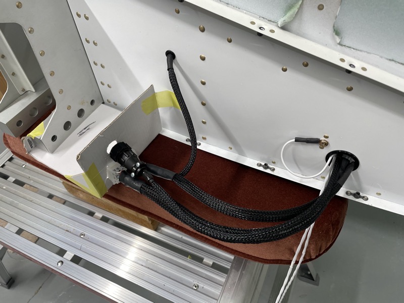
Here’s the left side completed.
There is quite a bit of jepardy involved doing this I decided … one false move (wires cut too short, pins in wrong holes etc) would involve a lot of hassle!
Note the earth wire link attached to the nutplate on the fuselage side. All my earth wires are heading to a grounding point up front … except the Fuel Tank Senders, which I have installed as per the manual and so are locally grounded.
The earth link just provides a wired earth path from wing to fuselage through one of the connectors. In the picture it looks as though it’s coming out of the fuselage, but actually it routes from the connector and loops back out just inside the Heyco Bush … I decided it was easier to shroud the cables doing it that way.
Same for the right side …
… all complete.
VHF Antennae Attachment

I purchased two Comant CI 122 VHF Antennae, and these have a 4 screw attachment rather than the 2 screw holes provided by the Vans attachment points under the joystick area on the lower fuselage.
But happily the rivets, which attach the doubler inside, have been spaced to perfectly match the industry standard profile … but they need drilling out of course.
Once removed I enlarged to holes to fit the attachment screws.
The large connector hole is also in the correct postion.
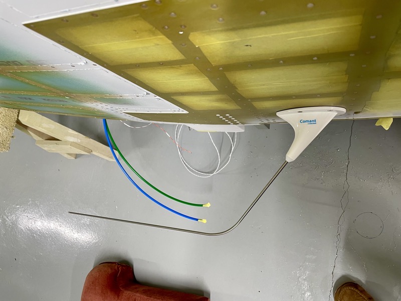
If fitting the VHF antennae underneath you need a “bent whip” design to ensure ground clearance.
VHF Antennae Cabling
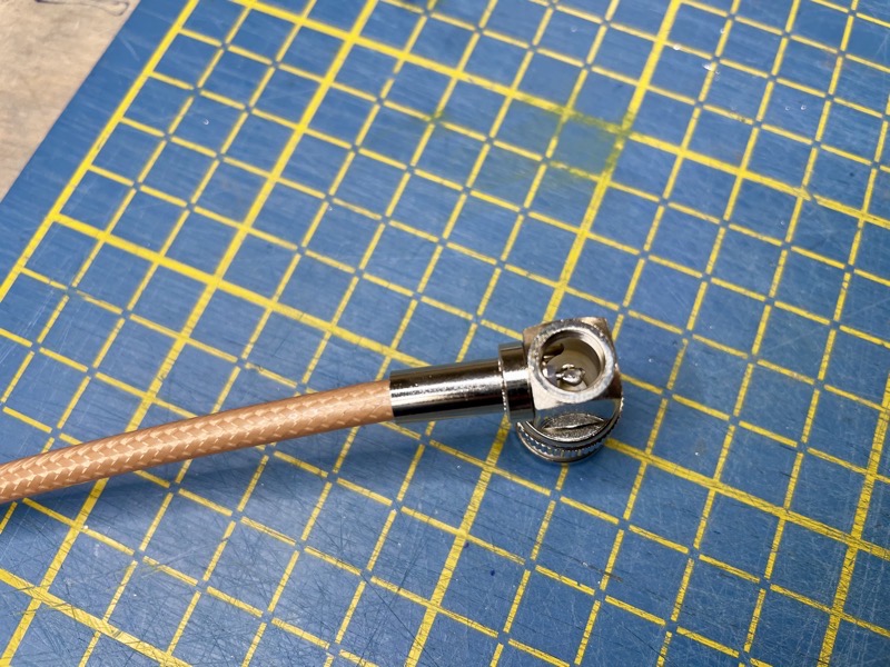
I decided to use 90º BNC connectors to ease the cable routing.
This involved some careful soldering down a hole!
Once crimped and soldered, the hole is sealed with a little screw cap. Don’t let any solder get on the thread!
Yep, I did on the first one … I had a great deal of difficulty removing enough to allow the cap to fit!!!

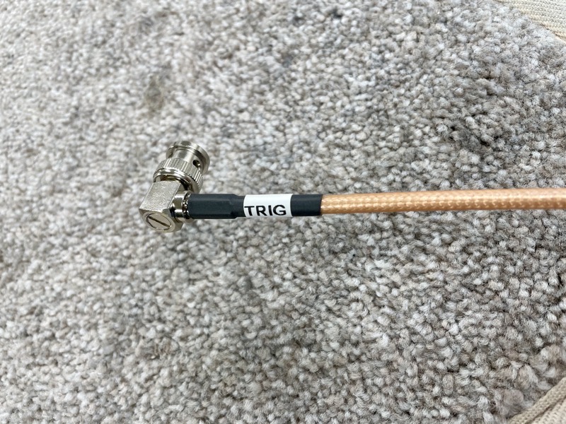
Worth the effort I reckon … the 90º connectors ensure a stress free route for the RG400 cable.
Standby Alternator LR4D-14 Voltage Regulator
My standby alternator and voltage regulator eventually turned up from B&C in the US, so I attached it to my door.
Happily my planning worked out and it clears the surround easily as the door is hinged back for access.


2 comments on Fuselage Wing Root Connectors & VHF Antennae
You can purchase 90 degree BNC adapters, I have used them on the 3 and they seem to work fine although there will be some loss I assume. Handy if you forget for future reference.
Good to know Chris : )