


Wiring – Planning the Backbone
Over the last few weeks I have spent many hours researching and planning the overall wiring architecture … the “Wiring Backbone”.
Consequently, there hasn’t been much actual progress in the workshop, which has been frustrating. But as many advise, time planning is well spent.
We decided a while ago to adopt the Vertical Power VPX/PPS system. The aim has been to use the advantages of the Electronic Circuit Breaker, together with the solid state electronics, at the same time keeping it as simple as possible.
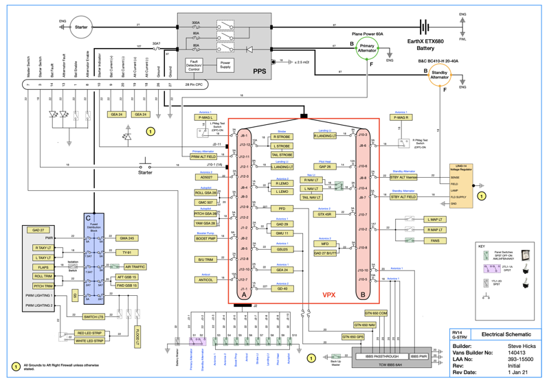
The diagram above (a PDF can be downloaded by clicking the image) will not make much sense unless you know a little bit about the VPX and PPS. Be aware it is still work in progress and not proven yet!
The VPX contains two independent BusBars A & B, and you will see I’ve included an independent BusBar C. This is not really necessary, as there is substantial redundancy designed into the VPX. But here in the UK the Light Aircraft Association are keen that if software controlled electrical devices are installed then there should be a plan B.
It is perfectly possible to wire the Flap control and Trims in the VPX, which provides very capable functions. Again, thinking ahead to possible UK IFR/Night approval, we decided to use a Garmin GAD27 powered by the Bus C to control these functions.
A standby alternator will provide redundancy, and also possibly enable a return to base during VFR in case of primary alternator unserviceabilty.
The PPS replaces the Battery Contactor, Starter Contactor, Alternator ANL fuses etc. In the unlikely event of a total PPS failure, then a TCW Independent Standby Battery System will provide power to the PFD, COM/NAV and engine indications long enough to land at the nearest suitable aerodrome.


One comment on Wiring – Planning the Backbone
Hi Steve….
This may be a minor point, but I’m struggling with where to place the grounding plate for my electrical system on my RV-14A. My harness was fabricated by SteinAir and I’m in the process of installing all the avionics. I’m satisfied with the locations of all the panel mounted and remotely mounted avionics, but this little detail has me scratching my head a bit. Any thoughts you have would be appreciated. Thanks Lew M